Technical
AD 281: The Use of Discontinuous Columns in Simple Construction
In recent years the use of discontinuous columns and continuous beams as a form of simple construction has emerged in the residential sector. This development has occurred for a variety of technical and commercial reasons; however, the form of construction need not be restricted to the residential sector alone. This AD provides general advice on construction for this innovation and is the first in a series. Subsequent ADs will provide advice on structural design, dealing with column design, connection design and robustness, and in-plane stability.
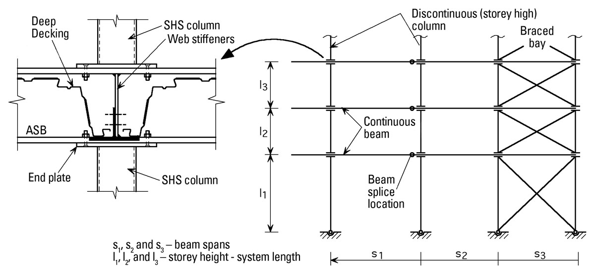
The principles of connections and bracings using discontinuous columns are illustrated in Figures 1 & 2 for a typical medium-rise project in the residential sector.

Figure 1: ASB Continuous Beam and Discontinuous (Storey-High) Tubular Columns

Figure 2: Floor Beam Splice Location and Details
Beams
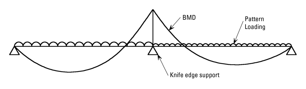
The floor beam in this form of construction may be designed as continuous, thereby either reducing the overall floor depth or increasing the beam spans. However, the loss of composite action in the hogging region of the beam must be allowed for in design if required by the floor system.
Transport restrictions or handling requirements often necessitate the inclusion of splices in the floor beams and these are located close to the beam column-connection as shown in Figure 2. These beam splices are designed and detailed as simple shear connections, assumed to act as ‘pins’ for flexure in the vertical plane, but also capable of resisting any additional axial forces and torque that may arise in the permanent or temporary conditions. Axial forces may arise from forces carried to the bracing system. Torque may arise from floor loading along only one side of a beam. This may occur on all beams during the construction sequence and also in the permanent condition for edge beams. Careful consideration must be given to the locations of the beam splices in relation to the braced bays as illustrated in Figure 2 in order to ensure a simple erection sequence. The frame should be analysed and designed for this arrangement of beam splices. Different ASB beams may be used in the same floor plate as a result of variation in loading intensity or span but will result in different column lengths for the same storey. It should be noted that ASBs are usually aligned so that the upper surfaces of the bottom flanges (the setting out levels) are at the same level and hence the top of steel level for the floor beams will vary.
Columns
Circular hollow section columns are often left exposed internally for clear floor solutions. Alternatively, RHS or SHS columns are chosen so as to be compatible with internal wall dimensions and to provide flat surfaces for fixing. In addition, the hollow columns may be concrete-filled offsite prior to erection if required for load capacity or fire resistance. It is prudent to have some rationalisation in the number of wall thicknesses used on a project where most of the columns will have the same nominal size. With standard column end plates, all the columns will look the same on site without a clear marking system and the risk exists that weaker columns will be used in the wrong location.
Column–beam connections
The column end plates are bolted directly to the flanges of the floor beam in the depth of the floor, often using countersunk bolts. This detail removes the inconvenience of obtrusive column splices using cover or flange plates. The rolled pattern on the top flange of the ASB beams has no effect on the transfer of axial load or shear in the connection. As the column end plates are connected above and below the floor beams, the beam’s rolling tolerance on overall depth as well as the fabrication tolerance on column length will affect the setting out level for each floor. In medium and high-rise projects, shims should be allowed for in the connection every few floors in order to ensure that the erected setting out levels for each floor are within tolerance. The combination of shims and tolerances will affect the diagonal length for brace members and hence it is prudent to use flats in cross bracing with this type of construction. Flats may be drilled on site to suit.
Stability
Clause 2.4.5.2 in BS 5950-1: 2000 requires that each column at each floor level be held in position in two directions and hence it is imperative that the RHS tie in Figure 1 or the Structural Tee in Figure 2 be used. This is particularly the case for the temporary condition in order to ensure a stable structure during erection and placing of concrete.
It is recommended that full depth web stiffeners are used at all column-beam connections unless the stability of the web against sway can be demonstrated in both the temporary and permanent conditions.
With regard to temporary stability it is necessary that the entire bracing system for a floor be installed before the concrete element of the floor plate is placed or poured. Additional temporary bracing is often required to assist with the lining and levelling of the structure during erection and this may double as temporary bracing for stability purposes.
Construction sequence
A construction sequence that allows steelwork to be erected from a completed floor plate will often be most convenient. In this sequence, two or three floors are completed before erecting the steelwork for higher floors. Note that pockets must be left in the concrete to allow the column endplate to be connected to the upper flange of the floor beam.

Related Posts
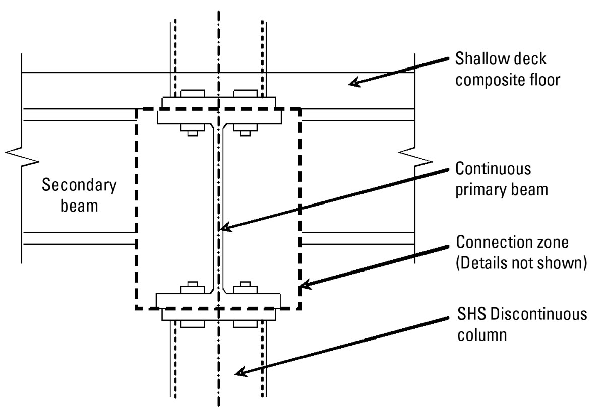
AD 292: The Use of Discontinuous Columns and Shallow Deck Composite Slabs on Floor Beams
AD 288: Discontinuous Columns in Simple Construction: Beam-Column Connection
AD 285: Floor Systems for Simple Construction using Discontinuous Columns and Continuous Beams
AD 283: The Use of Discontinuous Columns in Simple Construction