Technical
AD 283: The Use of Discontinuous Columns in Simple Construction
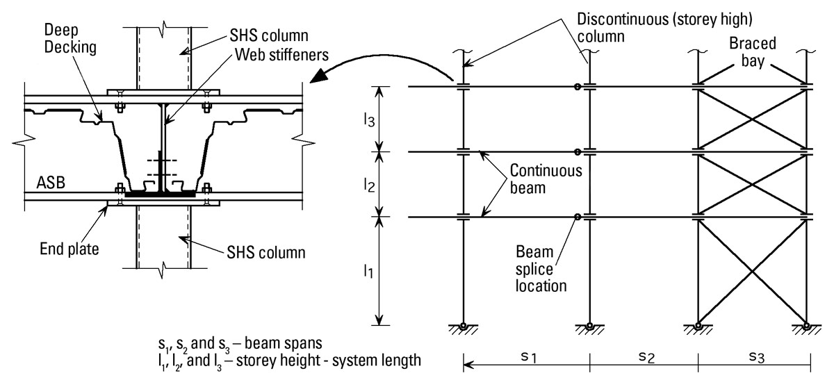
This AD provides advice on the design of discontinuous (storey-high) columns in simple construction. This is the second in a series of ADs dealing with discontinuous columns and continuous beams as a form of simple construction. General advice on this form of construction is given in AD 281 and the framing system and connection detail illustrated in that Advisory Note is reproduced here in Figure 1.
Columns in simple construction
Clause 4.7.7 of BS5950-1: 2000 gives the design rules for columns in simple construction and the assumptions that underpin this clause are explained in AD 275. A single interaction equation needs to be satisfied, encompassing both cross-section and member buckling checks. This is a safe and easy to use method, and should be applied to the design of discontinuous columns in this form of construction.
For circular and square hollow sections columns, Mbs should be taken as equal to the moment capacity of the cross-section Mc. For rectangular hollow sections, Mbs may also be taken as Mc subject to the limits of clause 4.7.7, clause 4.3.6.1 and Table 15. If doubly symmetric open sections are used, an equivalent slenderness λLT of 0.5 L/ry is taken in order to calculate Mbs (where L is the storey height).
The effective length of the column is required to determine its compression resistance and to check the slenderness limits in Table 15, if required.
The eccentricity of the beam reaction (relative to the column centreline) is required in order to calculate the nominal moments for use in the interaction equation.
Column effective length
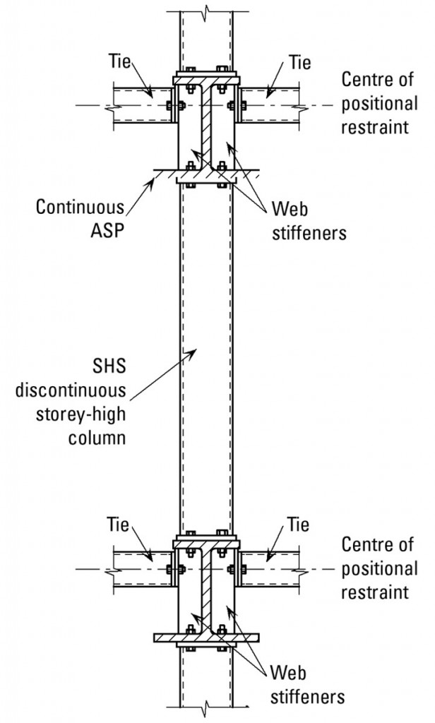
A typical storey-high column is shown in Figure 2. For this form of construction it should be assumed that the column is a pin-ended member (prop) and the effective length should be taken as the length between positional restraints. When similar depth beams are used in each floor, this is usually the same as the storey height (sometimes referred to as system length).
As mentioned in AD281, full depth web stiffeners are provided on the beams at the connections. This will ensure that the effective pin-ended column will have sufficient stiffness over its end portion (i.e. over the beam depth). The design of the beam-column connection will be covered by a future AD.
Positional restraint
In order to ensure that the effective length of a pin-ended strut may be taken as the system length, BS 5950-1 has particular requirements concerning restraint.
Clause 2.4.5.2 in BS 5950-1: 2000 requires that each column be held in position or laterally restrained in both directions at each floor level. The ties or concrete floor plate should be designed for the tying requirements of clause 2.4.5, as appropriate for the permanent condition. The ties should also be checked against the positional restraint requirements of clause 4.7.1.2 for both the permanent and, particularly, the temporary condition.
Members providing positional restraint should be connected to an appropriate shear diaphragm or system of triangulated bracing.
Column Design and Nominal Moments
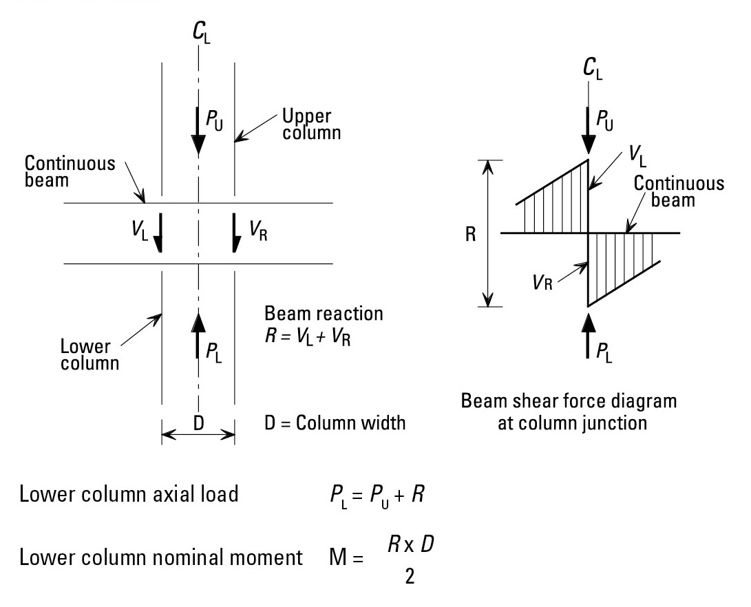
The loading at the beam-column interface is illustrated in Figure 3 and the following simplified design procedure is recommended:-
The lower column should be designed for the axial load PL and nominal moment M. Assuming that the centre lines from the upper and lower columns coincide, the axial load Pu from the upper column passes straight through the beam and therefore no moment is induced in the beam or in the lower column from the effects of Pu .
The nominal moments at the top of the lower column should be taken as the total beam reaction multiplied by half the column width. No nominal moment is taken at the bottom of the column.
Note: The floor beams in this form of construction may be designed as continuous and hence pattern loading must be considered in their design. However, it is not necessary to consider the effect of pattern loading on the column when determining the nominal end moments. Thus the beam reactions for use in column design will arise from the case where the beams on both sides carry their full loading. Note also that, in determining the reaction at the top of each column, the reaction under a beam that is analysed as continuous may be greater than if pin ended beams were assumed.


