Projects and Features
Design of composite beams with a reduced level of shear connection
Dr Graham Couchman considers SCI’s new publication P405 Minimum degree of shear connection rules for UK construction to Eurocode 4.
Background
Developments in decking products and UK construction practice have, in some cases, resulted in shear stud resistances dropping below the values that were traditionally used in design. Compared to re-entrant shapes of similar depth, trapezoidal decking has increased spanning ability and therefore permits wider spacing of secondary beams. These benefits result from the lower volume, and weight, of concrete that is needed. However, a downside of reducing the volume of concrete can be that there is less concrete around the shear studs on the supporting composite beams, and this reduces the resistance of the shear connection (which for typical building applications is governed by a failure surface of concrete). It is worth adding that the stud resistances given in EN 1994-1-1 (and for that matter BS 5950-3.1) are based on test results. The testing on which the current Eurocode rules are based was carried out over twenty years ago, self-evidently using products that were available at that time. The rules in BS 5950-3.1, prior to its amendment in 2010, are even more inappropriate when some forms of modern decking are used. Figure 1 shows the very ductile behaviour that can be achieved when a stud is placed in decking that runs transversally to the beam, and shows the impact of deck geometry. Failure is governed by the concrete, with two plastic hinges having formed in the stud.
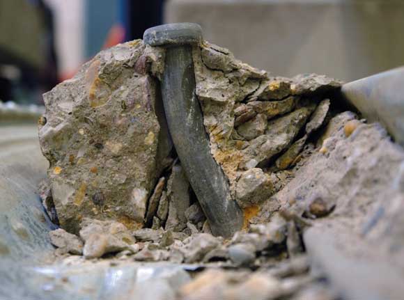
Figure 1: Failure of a shear stud placed in transverse decking (photo courtesy of University of Luxembourg)
Lower stud resistances can result in composite beam designs (that were previously possible) becoming impossible, not because insufficient force can be transferred between steel and concrete to generate the necessary moment resistance, but because the maximum number of studs that can be accommodated on a beam is often less than the number of studs needed to satisfy rules for minimum degree of shear connection. A pilot study carried out by SCI in 2013 identified that beams with transverse trapezoidal decking, of nominal height 80 mm, were a particular issue. This is a form of decking that is particularly beneficial from a composite slab point of view.
The need for a minimum degree of shear connection
When a beam is designed with full shear connection it means that there are sufficient shear connectors present to either fully exploit the steel section in tension or, as is more often the case in buildings, fully exploit the concrete slab in compression. A reduced number of shear connectors may be used, giving partial shear connection, when less force transfer between the steel and concrete is sufficient to achieve the necessary composite beam moment resistance.
However, it is important to recognise that a minimum degree of (partial) connection is absolutely necessary, in order to ensure there are sufficient studs present on a beam. ‘Sufficient’ has traditionally been taken as the number of studs needed to provide a collective stiffness to limit the slip between steel and concrete elements at the ultimate limit state to a certain amount. It is a resistance check to indirectly check stiffness, making it a rule that is easy to apply but difficult to understand.
In striving for reduced values of minimum degree of connection, it was necessary for SCI to consider an additional definition of ‘sufficient’, namely the number of studs needed to ensure that the connection remains elastic under serviceability levels of loading. A danger of this criterion not being satisfied would be that, under the unlikely event of repeated loading up to SLS levels, a ‘shakedown’ of the shear connection would occur (leading to cumulative and irreversible deflections).
Variables that affect the minimum degree of shear connection
The rules given in EN 1994-1-1 recognise that the minimum degree of connection is a function of steel strength, beam span, and any asymmetry of the beam flanges. However, a number of other variables affect the minimum degree, sometimes substantially. Recent work by SCI has considered; whether the beam is propped or unpropped, the slip capacity of the studs (which is greater when they are placed in transverse trapezoidal decking than the 6 mm assumed by EN 1994-1-1), and the type of loading. Consideration has also been given to beams with regularly spaced, large circular web openings (cellular beams), and beams that are only part utilised in bending.
Quantifying the effect of each of these variables, in order to develop design rules that allow for them, has been a major undertaking for SCI and has taken several years. The guidance that appeared on www.steel-ncci.co.uk (document PN002a-GB) in 2010 represented an interim step that has been extended by more recent work as presented in the new publication, SCI P405. Given the prohibitive cost of full scale physical testing of a large number of beams, finite element analysis has been used to perform comprehensive parametric studies. To calibrate the models, comparisons were made with work from independent research teams, and where possible beam tests. Of particular note in terms of beam tests are a 10 m span test carried out for SCI at Cambridge University in 2006, and two tests recently undertaken at the University of Bradford as part of a joint research project.
New rules for minimum degree of connection
The new rules developed by SCI, examples of which can be seen in Figures 2 and 3, may be considered to complement those given in EN 1994-1-1 by covering more alternatives than the simpler ‘cover all’ rules in the code (which as noted earlier only consider three variables). Before considering the rules it is important to recognise that they must be used in conjunction with; more onerous detailing rules for maximum stud spacing than are presented in EN 1994-1-1 (in particular with transverse decking there must be at least one stud per trough), and a requirement to consider the increased beam flexibility that results from a low degree of connection. The latter can be achieved using a rule taken from BS 5950-3.1 (Clause 6.1.4). All the rules have a practical, but limited scope. It is important that this is respected (see SCI P405 for full details).
Figures 2 and 3 show minimum degree of shear connection as a function of span for unpropped symmetric and asymmetric (bottom flange three times the area of the top steel flange) beams respectively. For levels of asymmetry less than three it is acceptable to interpolate between the asymmetric and corresponding symmetric curves. The curves that are labelled as ’10 mm slip’ should only be used when a beam has transverse trapezoidal decking. Some of the curves exhibit an absolute lower bound (that is independent of span), and this reflects the minimum connection needed to maintain elastic behaviour of the shear studs under service loading. Where the degree of connection varies with span it shows the requirement is needed to limit the maximum slip at the ultimate limit state.
Figure 2: Minimum degree of shear connection vs span for unpropped symmetric beams – slip capacity of the shear connection either 6 mm or 10 mm, composite beams either 100% or 80% utilised in bending
Figure 3: Minimum degree of shear connection vs span for unpropped asymmetric (1:3) beams – slip capacity of the shear connection either 6 mm or 10 mm, composite beams either 100% or 80% utilised in bending
Both figures include curves for beams that are 100% utilised in bending and 80% utilised in bending. This is a very important concept, which has major implications, and will be a useful tool for designers. Utilisation in bending is defined as the factored applied moment divided by the design moment resistance of the composite beam. Clearly this could be less than 100% if the design is governed by serviceability requirements, or if an oversize steel beam has been specified for some reason (including because the number of studs needed to meet minimum degree of connection requirements for a fully utilised beam cannot be accommodated). Because steel is a non-linear material, and the load-slip behaviour of shear studs is non-linear, reducing the utilisation of the beam (and so the stresses in the top flange) can have a disproportionate impact on interface slip and therefore the number of studs needs to limit this slip.
Studies have shown that the minimum degree of connection needed to limit slip at the ultimate limit state can be reduced as a function of the beam utilisation squared (this can be clearly seen in Figure 2, where the gradients of the ‘curves’ for 80% utilised beams are equal to 0.8² = 0.64 times those for fully utilised beams). Slip at serviceability loading is directly proportional to the utilisation (so in Figure 2 the horizontal part of the ‘curve’ for an 80% utilised beam is simply at 0.8 times the limit for the fully utilised beam). The findings concerning beam utilisation lend justification to, and in many case improve upon, the method that has been used by many designers of assuming an S355 beam is S275 in order to reduce the minimum degree of connection requirement to a level that can be satisfied.
The curves shown in Figures 2 and 3 apply to solid web beams. When regularly spaced, large circular openings are present in the beam web, less onerous rules may be used. This is because the strains in the top steel flange, which affect slip, are less than they would be in a corresponding situation with a solid web beam.
For full details of the scope within which these rules can be used, and indeed the comprehensive set of rules, reference should be made to SCI publication P405. It includes complementary guidance on shear stud resistance and detailing.