Projects and Features
Use of fibre-reinforced concrete in composite slabs (part 1)
Recent years have seen increasing interest in replacing the reinforcement mesh with steel fibres in composite slabs on steel decking. In this first of two articles, Constantinos Kyprianou, Principal Engineer at the Steel Construction Institute, provides an overview of the characteristics of the different types of fibres that can be mixed in concrete. Most of the information provided here has been gathered from publications by the Concrete Society [1].
Introduction
The use of fibres within the concrete mix, and in particular steel fibres, is not a new technology. The concept has been in existence for many years, while the first patent was granted in 1874[1]. Despite this, commercial use only took off in the 1970s, mainly in Europe, USA and Japan. Although fibre manufacturers have been producing guidelines for the design of pile and ground-supported floors over a number of years, an agreed design approach for steel-fibre-reinforced-concrete (SFRC) was published for the first time in 2003 by RILEM[2]. This design method[2] provides a methodology for determining the material properties of SFRC, a design approach for bending and shear at ultimate limit states and crack control rules for the serviceability limit states. This method was adopted and published in 2007 as guidance in TR34[3] and TR63[4] by the Concrete Society. Design of steel-fibre-reinforced concrete is not currently covered by design standards including the Eurocodes, where the only reinforcement considered is conventional steel bars or mesh.
According to the Concrete Society[1], in the UK, several millions of square metres of steel-fibre reinforced slabs for ground-supported and pile-supported applications have been constructed over the past decade. Precast elements and suspended composite slabs on steel decking are some of the other potential applications for fibre-reinforced concrete. For composite slabs with steel fibres the same methodology as in [2,3,4] for determining the material properties of SFRC is followed, while many of the concepts in the design approach are also adopted. However, some distinctions in design philosophy exist. For example, in the design of composite slabs at normal ultimate limit state the presence of fibres is typically (and conservatively) ignored. For the accidental fire limit state, the presence of fibres is, however, recognised and considered in enhancing the bending capacity of the slab at elevated temperatures. As such, fibres can play a critical role in the behaviour of a composite slab since not only do they control cracking but also provide an alternative to mesh reinforcement in the fire situation. Before jumping into more detailed technicalities of composite slab design with fibres, which will be reported in the second article, the different types of fibre and their associated characteristics should be defined.
Types of fibre
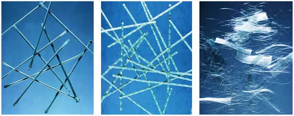
Three main types of fibre may be used in a concrete mix: steel fibres, macro-synthetic and micro-synthetic polymer fibres. In Figure 1 typical forms for each of these three main types of fibre are illustrated with photos of similar scale to allow comparison in shape and size. In accordance with BS EN 14889[5], steel fibres and macro-synthetic fibres provide post-cracking or residual moment capacity to concrete and as such can be used in the design of elements under flexure, whereas micro-synthetic fibres do not provide any post-cracking ductility and as such cannot be considered in structural design.
The required fibre dosage, specified in kg/m³, will vary depending on the type of application, concrete mix design and the performance requirements of each particular project. The main characteristics of the three types of fibre are described in the following sections.
Steel fibres
For composite slab applications, steel fibre dosage will typically be in the range of 20 kg to 40 kg/m³.
As per BS EN 14889[5], steel fibres can be classified into five groups, according to the method of manufacture, as follows:
- Group I: Cold-drawn wire
- Group II: Cut sheet
- Group III: Melt extracted
- Group IV: Shaved cold drawn wire
- Group V: Milled from blocks
Other common methods of characterisation, which describe shape, geometry and strength are:
- Cross-section: Round, flat, crescent, etc.
- Deformations: Straight, wavy, hook-end, double hook-end, etc.
- Length: 19 – 60 mm
- Aspect Ratio (length/diameter): 30 – 100
- Young’s modulus: 205 kN/mm²
- Tensile strength: 345 – 1700 N/mm²
Currently, fibre manufacturers produce steel fibres with diameters ranging between 0.5 mm and 1.0 mm and the most common lengths are between 35 mm and 60 mm; typical examples are shown in Figure 1 (a). Nowadays, the usual tensile strength range is between 1100 N/mm² and 1500 N/mm², but some examples of high-performance fibres report strengths of up to 2300 N/mm². Some of their physical characteristics directly affect key aspects of performance, such as the residual flexural tensile strength of steel-fibre-reinforced-concrete, while others are less important. A requirement set by BS EN 14889-Part 1[5] is for the supplier to declare the respective dosage in kg/m³ which achieves a residual flexural strength of at least 1.5 MPa at CMOD (crack mouth opening displacement) 0.5 mm and a residual flexural strength of at least 1 MPa at CMOD 3.0 mm, when tested in accordance with the standard notched beam test. Further information on the use of steel fibres can be found in TR34[3] and TR63[4].
Macro-synthetic fibres
Macro-synthetic fibres, illustrated in Figure 1 (b), are usually made from a blend of polymers and were originally developed to provide an alternative to steel fibres in some applications. They generally have a reasonable tensile strength (about 600 N/mm²) and a relatively high modulus of elasticity (about 10 kN/mm²), but when compared with the most modern high strength steel fibres they are lacking.
The properties of the fibres are covered by BS EN 14889-Part 2[5] and they have the same requirements for demonstrating residual strength as steel fibres. In addition, the manufacturer should demonstrate that the fibres are unaffected by the alkalis in the cement paste, and are resistant to moisture and to the substances present in air-entraining and chemical admixtures. They must also be resistant to chlorides when used in marine structures or those subjected to de-icing salts. Also, the effects of long-term creep of macro-synthetic fibres are thought to be significant and need to be considered. Further information on the use of macro-synthetic fibres may be found in TR65[6].
Micro-synthetic fibres
Micro-synthetic fibres are various types of short, thin and chopped polypropylene fibres, as shown in Figure 1 (c). Typically, they may be added to concrete at a rate of about 0.9 kg/m³ and they can be used along with steel-fibres. Their primary role is to modify the properties of fresh concrete. They increase the homogeneity of the mix, stabilising the movement of solid particles and blocking bleed water channels. This reduces the bleed capacity of the concrete and slows down the bleed rate, helping to reduce plastic settlement. Polypropylene fibres have a limited effect on the material properties of the hardened concrete and as such are not considered in design. They have been shown to reduce the spalling of concrete in a fire. One note of caution is that their use can reduce the slump of concrete as they act as a thickening agent.
Material properties of fibre-reinforced concrete
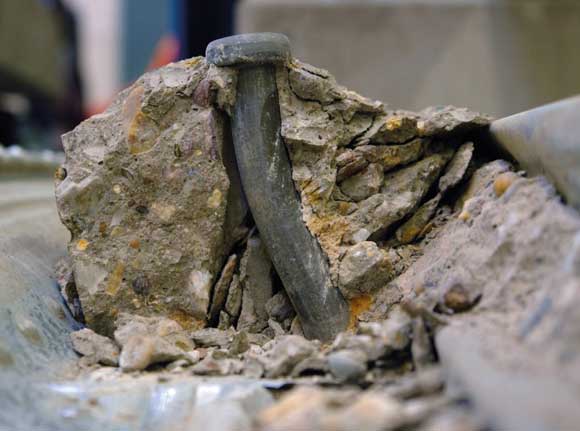
The effect of the fibres on the strength of the concrete is determined in accordance with BS EN 14845[7] using a standard notched beam test described in BS EN 14651[8]. Specimens 150 mm-wide × 150 mm-deep are tested under 3-point loading over a span of 500 mm. The specimens are notched with a 25-mm deep cut across their width at mid-length, and then tested with the notch in the tension face, as shown in Figure 2. A test set consists of at least 12 nominally identical samples, i.e. same dosage and compressive strength of concrete.

The crack mouth opening displacement (CMOD) (i.e. the increase in width of the notch) and the load F are recorded at CMODs of 0.5, 1.5, 2.5 and 3.5 mm. A typical graph of applied load FR against CMOD is shown in Figure 3.
Maximum applied load (FL ) is achieved at the point just before the concrete beam cracks. Typically, the capacity of the section reduces as strain and crack width increases, but certain combinations of fibre type and dosage can exhibit strain hardening behaviour. Strain hardening is identified in a notched beam test when F1 is equal to or greater than FL and F4 is greater than F1.
Residual flexural strength fR in N/mm2 is derived using the following equation[2,3]:
where:
FR is the applied load at the respective CMOD stage, i.e. for CMOD₁ this is F1,
l is the span of 500 mm,
b is the width of 150 mm and
hsp is the depth of the section at the notch, i.e. 150 – 25 = 125 mm.
The residual strengths fR1, fR2, fR3 and fR4 for each CMOD are reported as the mean values from all 12 tests of a set with the same dosage. Tests should cover the whole range of fibre dosages to be used. Interpolation between results for different dosages can be made, but not extrapolation. Also, the range between test results when interpolation is made should not be greater than 10 kg/m³[3].
Commentary
This article has reviewed the characteristics of the main type of fibres and the established test method to determine the material properties of fibre-reinforced concrete. In the second part of this two-part article, design and construction considerations will be explored.
References
- Concrete Society. Accessed: 9/11/2022, www.concrete.org.uk/fingertips.asp
- RILEM, 2003. TC 162-TDF, Tests and design methods for steel fibre reinforced concrete, σ-ε design method, Material and Structures, Vol. 36, pp. 560-567.
- Concrete Society, 2018. Concrete Industrial ground floors, 4th edition. Technical Report No. 34.
- Concrete Society, 2007. Guidance for the Design of Steel-Fibre-Reinforced Concrete. Technical Report No. 63.
- BSI, 2006. BS EN 14889. Fibres for concrete, Part 1: Steel fibres – definition, specification and conformity, Part 2: Polymer fibres – definition, specification and conformity.
- Concrete Society, 2007. Guidance on the use of Macro-synthetic-fibre-reinforced Concrete. Technical Report No. 65.
- BSI, 2006. BS EN 14845. Test methods for fibres in concrete, Part 1: Reference concretes, Part 2: Effect on strength.
- BSI, 2005. BS EN 14651 + A1: 2007. Test method for metallic fibered concrete. Measuring the flexural tensile strength (limit of proportionality (LOP), residual).
- Matest SpA. Accessed 10/11/2022, CMOD test www.youtube.com/watch?v=wlBFZw_bryE