Projects and Features
The use of semi-continuous joints to reduce steel weight and cost
Graham Couchman of the SCI revisits a publication from 1997 which, as we become increasingly concerned with embodied carbon, and therefore efficient use of materials, may be more relevant now than it has ever been. The design guidance offers the potential to significantly decrease beam weights, with no increases in joint complexity and cost, and only marginal increases in frame analysis and design complexity.
Introduction
Has the time finally come for semi-continuous frames? BCSA’s UK structural steelwork: 2050 decarbonisation roadmap 1, produced with input from SCI and launched at the end of 2021, identified ‘design efficiency’ as one of the key ways for steel construction to achieve its targets. Design’s estimated potential to contribute 18% of the ‘change’ needed is clearly very significant, and much of that potential is available to be exploited right now. SCI’s guide to Semi-continuous Braced Frames (P183) 2 was published in 1997, and remains entirely valid. It was written at a time when SCI was focused primarily on ‘structural engineering’, and had only one or two experts working on ‘sustainability’. Today these previously separate disciplines have effectively merged as far as much of the guidance and advice SCI offers is concerned, with a major focus of the steelwork industry in the UK now being ‘sustainable structural engineering’.
Reducing the weight of steel by 18% may sound a lot, but Prof Julian Allwood and his team at the University of Cambridge have published a number of papers 3, suggesting that UK steel construction designers use nearly twice as much steel as necessary in order to satisfy design codes and regulations. Clearly this number depends on the building type, and would not apply to single storey industrial buildings. Much overdesign is down to non-technical issues, including low design fees, and the order of the design and procurement process (which means some loads are unknown at the time of design so blanket values are used, and designers are tempted to include some ‘bunce’ to accommodate subsequent changes of specification without needing to re-design).
There are two obvious results of low design fees, which are paid without recognising the correlation between the time spent on design and the ‘quality’ of the outcome. These results are, designing the most heavily loaded element of its type (e.g. a beam in a floor zone) and using the same size for other elements, and making the assumption that the joints are nominally-pinned. The latter choice makes the frame design simple in two senses of the word – easy to do (because there is no stiffness continuity between members), and ‘simple’ as such frames are known. Simple design is also chosen because it is recognised that much of the fabrication cost of a frame is associated with the joints, so complexities such as stiffeners and haunches are best avoided. The common split of responsibility between design of the beams and columns, and design of the joints, is also unhelpful if trying to develop a solution that optimises the member and joint ‘sizes’ and recognises the interaction between them . Assumed zero moments in the joints of a ‘simple frame’ mean that sagging moments in the simply-supported beams are maximised for a given level of loading. Rigid joints, used to produce continuous construction, are not used in braced frames unless exceptional circumstances dictate.
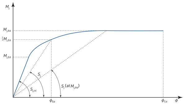
Semi-continuity offers many of the benefits of continuity, in terms of reducing beam sagging moments, deflections and therefore sizes, whilst retaining most/all of the benefits of simple construction in terms of fabrication cost and erection ease. This is because many so-called pinned joints, perhaps with some ‘thickening’ of components, do in fact offer reasonable stiffness and strength. Stiffeners and haunches are not needed to achieve very beneficial stiffness and strength – semi-rigidity and partial strength respectively, to use terminology from EN 1993-1-8. Figure 1 shows a schematic representation of the moment-rotation behaviour of a semi-continuous joint, illustrating the characteristics of stiffness, strength and (of equal importance, but often forgotten and very difficult to accurately predict) rotation capacity. The stiffness reduces from an initial elastic value, through ever decreasing secant values as the applied moment increases and the joint moves from elastic to elasto-plastic to plastic behaviour.
P183 describes how to apply semi-continuous design to braced frames. The key steps are summarised below. It is based on the premise that standard joints will be used, but 25 years after it was published we should be able to offer greater design/detailing freedom.
SCI has previously published guidance on semi-continuous unbraced frames 4, based on the so-called wind-moment method. Some readers may know that this is a very opaque way of designing frames, where assumptions are made that implicitly ‘give the right answer’, but clearly don’t represent what happens in reality. The wind-moment method was widely used in the days of ‘hand calculations’, and may still have a place as even today explicit design of semi-continuous unbraced frames is extremely complex (because of the load-unload behaviour of the joints under load reversal, which results in varying stiffnesses and ‘shakedown’). Care should be taken to ensure that a given design falls within the scope of application of the wind-moment method, with particular attention drawn to the need for fixed base columns.
How to do it?
P183 was written at a time when it was envisaged hand analysis and design would be adopted. Although today one would imagine that software might well be used for semi-continuous frame design, P183 (and the notes below) contains much useful information and guidance. Its Section 6 describes the design procedure in only two pages, with the stages summarised below. These are presented as a ‘teaser’ to show designers the ease and potential benefits, and encourage them to study the complete guidance.
Scheme design
Select column sizes to resist axial load alone in an overall buckling check. The utilisation of perimeter columns should be limited to 0.8, to allow some reserve for applied moment. The utilisation of internal columns may approach 1.0 (a lower value should be used for columns in an unbalanced situation, for which guidance is also given in P183).
Select Class 1 or 2 beam sections, based on the following criteria and the assumption that the beams will be restrained against failure in lateral torsional buckling:
Internal span Mpl,Rd ≈ 0.70 MEd
External span Mpl,Rd ≈ 0.80 MEd
Where:
Mpl,Rd = moment resistance of the beam
MEd = free bending moment at ULS
Final design
Joints
Select standard joints from the design tables provided in P183. Note that these are the same as the so-called wind-moment joints specified in the ‘Green Book’ 5, and, although this is a BS 5950 orientated guide, the resistances are based on the EN 1993-1-8 component method and are ‘Eurocode compatible’. The minimum joint moment resistance must satisfy the shortfall between the maximum applied moment and the moment resistance of the beam. Doing so means that no further check of the beams is required for the ULS. This highlights the interdependence of joint and member design, both of which should be carried out by the same ‘person’ for a semi-continuous frame.
The joint moment resistance should not exceed 50% (i.e. 50% partial strength) of the beam resistance for a joint to an internal column. The moment resistance of a joint to an external column should be approximately 20% of the beam resistance.
Check the joint shear resistance (using the design tables for standard joints), and add ‘shear bolts’ if necessary.
Beams
Calculate beam deflections under imposed (SLS) loading, using appropriate formulae and deflection coefficients as given below. Beams should be thought of as being rotationally restrained at the supports by springs. The spring stiffness represents the stiffness of the joint itself, plus that of the adjoining structure. Because of this stiffness, beam behaviour lies between ‘built-in’ and ‘simply supported’.
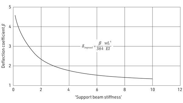
The graph shown in Figure 2 is taken from P183 and shows that not a lot of support rotational stiffness is needed to significantly reduce the beam deflections.

(internal span subject to UDL)
For the analysis of orthodox frames (as defined in P183), there is no need for the designer to determine an effective support stiffness provided the standard joints are used. The formulae below may be used for beams subject to uniformly distributed loading (other load types are considered in P183). The coefficients used in these equations are a conservative approximation, but P183 includes rules that allow stiffness of a particular situation to be taken into account explicitly for more accurate results (P183 Appendix B.2 states how to combine joint, column and beam stiffnesses to determine the equivalent stiffness of the rotational support).

For an internal span:
with joints having a partial strength in excess of 45%, β = 3.0
with joints having a partial strength less than 45%, β = 3.5
For an external span:
with joints having a partial strength in excess of 45%, β = 3.5
with joints having a partial strength less than 45%, β = 4.0
The relevance of using standard joints to justify the use of the relationships above is that they have a known (from testing) relationship between stiffness and strength, so can be chosen based solely on the latter. Guidance is given in P183 that would enable other joints to be used with stiffness and strength considered explicitly. The third key characteristic of a joint should not be forgotten even though rarely quantified – namely rotation capacity. Because the joints are partial strength they will normally be the location of the first plastic hinges, and so must be able to rotate sufficiently. The detailing of the standard joints means they are known, through testing, to be able to do this.
It is worth commenting on the UK National Annex to EN 1993-1-8 6, and what this means for the use of non-standard joints. Whilst explicitly allowing the use of semi-continuous design, it states that ‘until experience is gained with the numerical method of calculating rotational stiffness given in BS EN 1993-1-8, semi-continuous elastic design should only be used … where supported by test evidence … (or experience)’. Although this was published some time ago, it is doubtful that much experience has been gained. But of course the procedure described in P183, and here, does not use elastic design for ULS – the joints are behaving plastically well before collapse so their initial stiffness is irrelevant. Some inaccuracy when calculating deflections is part of structural engineering, not just limited to semi-continuous design. Indeed assuming joints are pinned, i.e. have zero stiffness, will always lead to an overestimation of deflections, with considerably greater inaccuracy than one would expect with semi-continuous joints designed using EN 1993-1-8!
Once deflections are determined, they are checked against limits as usual. Dynamic checks should also be performed (noting that whether joints are pinned, semi-continuous or continuous they behave as if they were rigid when subject to dynamic loading).
Columns
Check internal columns for overall buckling under the applied axial load in combination with any moment about the major axis resulting from unequal joint strengths, and any unbalanced minor axis moments. Minor axis moments should be calculated and distributed as in simple design (there are no standard details for minor-axis semi-continuous joints, though they might be envisaged), assuming eccentric beam reactions. The internal columns should also be checked for local capacity, considering axial loads and moments under pattern loading. Simplified procedures are given in P183.
Check perimeter columns for the applied axial load in combination with any major or minor axis moments. Both overall buckling and local capacity checks are required.
Check that the column sizes identified in the final design are compatible with the joint details, preferably without the need for column stiffening.
Details
Design the column bases, column splices, and the frame bracing systems as in ‘simple construction’. The detailing of bases and splices, which may be pinned or chosen to provide moment continuity, must be properly reflected in the frame analysis and design assumptions. Care should be taken if semi-continuous joints are used as part of the bracing system, because the behaviour of the joints may be adversely affected by either the presence of additional axial or shear loads in the beams, or detailing to accommodate the bracing members.
What now and next?
A simple illustration of the benefits to be had from using semi-continuous design, rather than simple design, can be gained by considering the reduction in beam size that could be possible due to the use of the β values given above for deflections (as β goes down, the second moment of area can follow it and still result in the same deflection). A 457×152×82 UB has a second moment of area of 36,588 cm⁴. If used in a frame with semi-continuity such that the β value dropped from five to three, this beam could be replaced by a 406×178×60 (second moment of area 21,596cm⁴). So a saving of 22 kg/m (almost 27%) for this simple comparison assuming deflection was critical. If we use beam weight as a simple representation of embodied carbon for the two cases, we can see how semi-continuous design could be highly relevant for future designs.
In 2022 SCI and BCSA will be working together to produce guidance on ‘design for sustainable steel construction’. This will include a more detailed review of the semi-continuous frame design principles and rules. Unlike 25 years ago, designers today can use tools to determine joint strength, stiffness and rotation capacity, although levels of accuracy (of the last two) may be open to some question. SCI will be developing an easy-to-use tool, using Trimble’s TEDDs platform, in 2022. This will allow key characteristics of ‘typical’ types of joint to be determined using the well-accepted EN 1993-1-8 component method. As TEDDs is part of the Trimble family this may also allow integration with their frame analysis and design software, which will really make semi-continuous design simple.
References
- UK structural steelwork: 2050 decarbonisation roadmap, BCSA, 2021
- Design of semi-continuous braced frames, P183, SCI, 1997
- Dunant, C., Drewniok, M., Eleftheriadis, S., Cullen, J., & Allwood, J. M. (2018). Regularity and optimisation practice in steel structural frames in real design cases. Resources, Conservation and Recycling, 134 294-302
- Wind-moment design of low-rise frames, P263, SCI, 1999
- Joints in steel construction – moment connections, P207, SCI, 1995
- UK National Annex to Eurocode 3: Design of steel structures. Design of joints, BSI, 2013


