Projects and Features
The New Bullring Shopping Centre

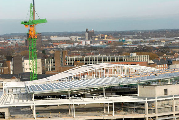
Fig 1: View of the Bullring Shopping Centre during construction, showing the arched trusses
The Bullring Shopping Centre in Birmingham consists of approximately 170,000m² of retail space. It comprises an open central street with glazed roofing over three shopping malls, four retail levels, a two-level car park, and a basement service yard. It contains 15,500 tonnes of structural steelwork. Alan Pottage reports.
FACT FILE: Bullring Shopping Centre, Birmingham
Architect: Chapman Taylor
Design and Management: Sir Robert McAlpine
Civil & Structural Engineers: Waterman Partnership/Arup
Building Services Engineer: WSP Group Steelwork
Contractor: Severfield-Reeve Structures
The building is situated in the busy commercial centre of Birmingham. Consequently, the programming of its construction and the logistics of delivery of materials to the site was vital to ensure the project’s timely completion with as little disruption as possible to the normal day-today activities of neighbouring commercial operations. In addition, the nature of the new shopping centre meant that access for pedestrians was to be more “user-friendly” than the previous building it was to replacing. Design
In order to achieve ease of access, a major road that ran beneath the site had to be lowered so that pedestrians could approach the centre at the same level as the surrounding streets. This road followed the route of two railway tunnels that provide access to New Street station, and as some of the retail areas of the new centre were to be situated directly over the road, a solution was needed to span both road and railway tunnels. The road was lowered to a level that was almost level with the roof of the railway tunnels.
Piles were installed between the railway tunnels to carry the loads from four 45m long triangular section arched steelwork trusses from which were suspended two levels of retail areas (fig. 1).
The booms of the arched trusses were 600mm diameter circular hollow sections, up to 60mm wall thickness, with internal (web) members between 210mm and 325mm diameter. Their size dictated that they were transported to site piece-small, and welded on site. Each fully fabricated arched truss weighed approximately 120 tonnes.
Fabrication
In order to carry out the fit-up and welding of the trusses, several temporary works structures were erected so that the trusses could be fabricated in the “upright” position, with the apex of the triangular shape pointing downwards. These temporary works structures were located as close to the trusses’ final erected position as possible. Boom sections were joined together by means of full penetration butt welds. The ends of the web members were profiled to suit the geometry of their intersection with the boom, and were connected to the boom using standard fillet welds.
These trusses also required the site application of an intumescent coating for fire protection. Individual pieces were delivered to site with an already applied compatible primer. Once site welding had been completed, the areas in the vicinity of the welds were made good with a similar primer, and the application of the intumescent coating took place. In order to ensure controlled conditions for both application and subsequent curing of the intumescent, the temporary works were “tented” both to protect the trusses from the elements and to provide an environment which would maintain an acceptable curing temperature provided by mobile heating equipment situated within the tent. Each truss took approximately eight weeks to fabricate, paint and erect on site.
Erection
Erection of the arched trusses took place during a night time possession of the site, using a “contract lift” that employed two cranes of 500 and 800 tonnes capacity (fig. 2). In order to carry out the erection, the cranes were situated on the road over the railway tunnels described above.

Fig 2: Erection of the arched trusses
Outriggers were placed on substantial spreader pads; in certain instances, due to the road’s gradient, the outriggers had to be situated on a temporary works structure to achieve as level a surface for the cranes as possible. During the lifts, monitoring of the railway tunnels took place to check for any untoward movements.
Completion of the erection was achieved by the use of ten tower cranes positioned within the site. Feeding such a city centre site with timely deliveries of steelwork, in the correct sequence and at the correct off-loading point was a key factor in achieving the overall site programme referred to above.
The feeding of the ten tower cranes – six of which were working at full capacity at any one time – was a major exercise in planning and logistics that had begun at an early stage. Close liaison with the staff of main contractor Sir Robert McAlpine during the erection period also ensured a minimum of disruption to the dayto- day site activities of other trades. During the construction period the tower cranes were supplemented by several mobile cranes of varying capacity.
Steelwork
A concrete frame forms the structure of the two lower levels; the three upper levels are constructed with structural steelwork. Between levels four and five, the structural grid has been rotated through 45º in order to align the centre with the existing street layout. This was achieved by using steel transfer structures to facilitate a load path from the steel superstructure to the supporting concrete frame.
A large proportion of the structure comprised typical beam-and-column construction, with lateral stability being provided by braced steelwork cores. Beam-to-beam and beam-tocolumn connections typically comprised flexible end plate connections. Column splices were formed by using internal flange plates with countersunk bolts to minimise the overall enclosing dimensions of the column shafts.
Special details

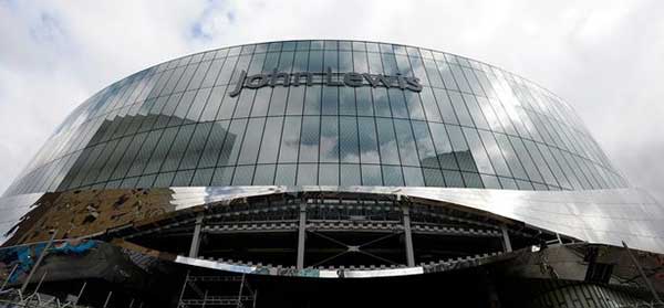
Fig 3: The Selfridges store

Fig 4: Bespoke plate girders

Fig 5: Plate girders with provision for services in the web
As is usual in the development of retail complexes there are several flagship stores that take up some the available retail space, invariably bringing along a need to accommodate a signature building form. In the case of the Bullring development, the Selfridges store was of a somewhat different construction from the other parts of the site (fig. 3).
The Selfridges store was curved both on plan and in elevation. Internal atria that facilitated the movement of customers within the store also exhibited a curved form. The extremity of both the store and the atria were cantilevered off the main structural frame.
To make these shapes, fabricated steel plate girders were incorporated into the structure. Around the atria, these were tapered. Within the store’s footprint, plate girders incorporating service openings facilitated integration of services with the structure. Services could run in the void provided by the structural form (fig. 4) or in the pre-formed service penetrations (fig. 5).
A notable project
As outlined above, the project comprised some 15,500 tonnes of fabricated structural steelwork which included 3,400 tonnes of bespoke plate girders together with approximately 120,000m² of composite floor decking and some 550,000 shear studs. Erection of the steelwork began on 28 June 2001, and was substantially complete within the agreed 40 week erection programme.
Alan Pottage is R&D Director of Severfield-Reeve Structures.
Reference:
1. “Cutting through the Bull” – Building – 9 August 2002