Projects and Features
Construction of the Boyne Bridge

Environmental constraints prevented this very large cable-stayed bridge from being assembled by normal techniques. It had to be put together on one side and launched across the valley. Nigel King reports.
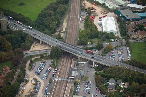
Ireland’s largest cable stay bridge is under construction in the peaceful Boyne Valley on the outskirts of Drogheda, an historic town situated 30 miles north of Dublin. This landmark steel structure will carry the M1 motorway linking Dublin and Belfast across the River Boyne.
The contractor for the €34m project is SIAC Cleveland Bridge Joint Venture, consisting of Irish contractor SIAC Construction Ltd. and Darlington based Cleveland Bridge UK Ltd.
The completed Boyne Bridge will consist of an asymmetric 56 cable stayed structure with a main span of 170m across the two channels of the river. A series of shorter approach spans constructed on piers carry the bridge over the northern slopes of the river valley.
Design
The client, Meath County Council, and its consultant, Northconsult, were determined to deliver a structure of aesthetic and technical merit. An innovative feature of the design is the GRP (Glass Reinforced Plastic) enclosure which surrounds and protects the steelwork of the superstructure whilst providing an aerodynamically and aesthetically enhanced profile. The detailed design continued the innovation with the use of a tubular steel space frame within the GRP enclosure to support the concrete deck slab. The tenders for the contract were invited on the basis of this design and SIAC Cleveland Bridge Joint Venture submitted the winning bid.
At the time of tender it was realised that the innovative space frame design still had significant technical, cost and time risks attached to it. In order to address these risks, Cleveland Bridge and its internal design consultant, Dorman Long Technology, began to develop an alternative design based on the use of a combination of twin longitudinal plate girders and cross girders.
Throughout the tender period, a considerable amount of effort was put into deriving the best method of erecting the cable-stayed superstructure. Ground level access into the main span was prohibited for environmental reasons, thus ruling out any support or delivery of material from below. Difficulties were envisaged with the adoption of the traditional progressive cantilever method normally used for cable stayed bridges, by erecting the tubular steelwork piece-small or in sub-assembled units. This led to the innovative method of assembling the main and back span deck behind the southern abutment and launching it across the river.
By the time the client was ready to place a contract for the Boyne Bridge, the alternative design was completed in order to present it for consideration. The scheme had advantages of maximum off-site fabrication under controlled conditions and reduced technical, cost and time risk. However, the appearance remained unaltered as all changes were within the GRP enclosure. The innovative launch scheme was still viable and was proposed as an integral part of the design. The proposals proved attractive to the client and were accepted early in the contract.
Being in control of the erection scheme and permanent works design allowed the designers to optimise the sections of the longitudinal girders by choosing the stress condition for the girders at the end of the launch and the finished cable stay loads. All design work was done in-house with a small team of engineers.
Launching
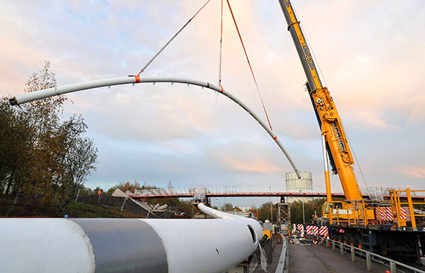
It was proposed to launch the assembled main and back span deck steelwork, weighing 1,600 tonnes and 210m in length, through the Aframe pylon and across the river to meet the north deck. The north deck would be erected independently prior to the launch.
The development of the launch scheme considered various options for the rolling support of the steelwork behind the abutment and at the pylon, along with those for positioning the temporary cable stay attachments and strand jacks. Detailed operational and risk assessments resulted in the selection of the following arrangements:
- Multi-axle trailers carrying, driving and steering the rear end of the steelwork on the approach to the southern abutment
- Rollers fixed to the steelwork running on steel tracks along the southern abutment and recycled as the launch progressed
- Rollers fixed to the pylon cross beam over which the girders passed
- Lateral guide systems at the southern abutment and pylon
- Temporary cable stays attached at ²⁄₅ and ⁴⁄₅ points on the main span with strand jacks mounted and operated at deck level
- A hauling line running from the launch front to a fixed point behind the northern abutment and operated by strand jacks. To facilitate the launch temporary works, an area of approach road, 160m in length, was prepared with compacted stone behind the southern abutment. A series of steel support stillages were set up to the pre load camber of the completed deck. The pre-fabricated longitudinal and cross girders were shipped from Cleveland Bridge and set up on the stillages
At the southern abutment and pylon crossbeam, temporary steel posts were cast into the concrete works to support the deck in both lateral and horizontal movement. On the north deck, the hauling line jacking system was cast into the concrete deck and anchored by means of embedded blocks behind the northern abutment.
Prior to launch operations, a series of checking points were set up along the deck to monitor the geometry of the deck at any stage. The pylon verticality was also checked for deflection at each stage.
Once the deck was pulled past the southern abutment, the temporary beams were installed to enable the whole deck to be lowered down into the final position at the southern abutment. With the aid of two ‘A’ frames as support, the deck was jacked down and then pulled back into the final position. After lowering down, the north deck was jacked back on the pier bearings to align with the launched steelwork. The final north and south deck connections were then welded.
Control of the launch
A step-by-step non-linear structural analysis produced the detailed step-by-step adjustments required at the strand jacks to control the launch progress whilst maintaining acceptable stresses in the steelwork. These were included with a comprehensive method statement and the detailed temporary works drawings.
All designs were independently checked and verified and a design team presence on site throughout the launch ensured accurate implementation. The check surveys undertaken at regular intervals throughout the launch showed excellent agreement with predicted profiles.
Cable installation

The final involvement of the design team was during permanent cable stay installation. Control of deck geometry during cable installation is one of the key features of this form of structure. Completion of the steelwork prior to any deck slab or cable work had the advantage of eliminating the potential errors in constructing the required unstressed girder shape usually present when erecting piece by piece in cantilever. Nevertheless considerable analytical effort was put into the prediction of geometry, cable loads and deck stresses and their sensitivity to variables such as temperature, weight errors and geometric construction tolerances.
Analysis of the surveys following cable tensioning was completed in the same morning allowing adjustments, if any, to be made that afternoon with no break in the construction work. Again the comparisons between actual and predicted geometry and cable loads were excellent.
Completion
The launch of the back and main span deck was completed successfully, followed by concreting of the deck. The in-situ concrete deck slab was poured incrementally in conjunction with the installation of the permanent cable stays. Installation of the barriers and asphalting, etc. is now well underway and the bridge is due to be completed by the end of April 2003.
Nigel King is a Project Manager with Cleveland Bridge UK.
The following people contributed to this article: Simon Hill, Survey Manager, Cleveland Bridge UK Ltd. David Taylor, Principal Engineer, Dorman Long Technology.