Projects and Features
Steel construction with trusses
Richard Henderson of the SCI discusses the use of trusses in buildings
1 Introduction
Trusses have been used in construction for centuries, originally manufactured from timber and used to form pitched roofs. Early truss railway bridges in the United States were constructed of timber and iron rods. With the development of wrought iron, truss bridges in this material were built in large numbers from the 1870s. The Forth Bridge was the first major steel bridge adopting truss construction and opened in 1890.
Steel trusses in buildings are used extensively to cover large clear spans and this article will mainly focus on this sort of construction.
2 Roof trusses
Roof trusses are an efficient means of supporting a roof covering for spans upwards of 20 m. Upper bound spans of 100 m are suggested on the steelconstruction.info web site. The upper limit is in fact dictated by the value and utility to the building user of the clear span and enclosed volume because examples of truss bridge construction illustrate that much longer spans are possible.
Space trusses and diagrids have been used to form two-way spanning roofs but the most common arrangement of truss roof construction uses one-way spanning elements. A common form of truss is the Pratt truss (or N frame) with vertical shear elements in compression and diagonal shear elements in tension.
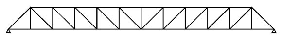
Figure 2.1: Pratt truss
Another is the Warren truss with all shear elements inclined at the same angle to the horizontal in alternating tension and compression from the support to mid-span of a simply supported span.
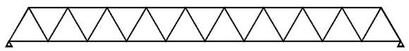
Figure 2.2: Warren truss
Primary trusses are commonly spaced at about one quarter or one fifth of their span but consideration should be given to the form of the secondary elements and roof decking when choosing the truss spacing as it is usual to have no more than two “layers” of structure supporting profiled roof sheeting. Deep-profile decking is capable of spanning five metres or more depending on the loading and can therefore be used with secondary elements spanning 20 metres or more between long-spanning primary trusses.
The span to depth ratio of trusses ranges from 10 to 25, depending on the intensity of the applied load. The lower the ratio, the longer are the shear members in the truss and the larger is the volume occupied by the roof structure. However, the load in the truss booms is lower in a deep truss so there is a trade-off between the truss booms and the members carrying shear forces. The slope of the top boom must also be considered because for a long span truss the increase in depth from eaves to mid span can be significant. The slope must also allow rainwater run-off to occur without ponding.
3 Truss modelling and analysis
The first step in modelling trusses for analysis, when designing to EN 1993-1-1 is to classify the joints in accordance with clause 5.1.2. If the joints are classified as fully pinned or fully fixed, the stiffness of the joints does not need to be taken into account in the global analysis. If the joints have an intermediate stiffness, the moment-rotation curve of the joint does affect the results. It is usual to choose fully pinned or fully fixed joints as the moment-rotation characteristics of the joints are not normally known. A common arrangement is for the tension and compression booms to be modelled as continuous with the bracing members pin ended because this matches the usual built arrangement.
Hand analysis of statically determinate trusses can easily be made if all the joints are assumed to be pinned and computer modelling can follow the same approach. The axial forces found in the members will be slightly higher following this approach than if all the joints are assumed fixed. Appropriate releases must be included in the analysis model, e.g. a roller support at one end. Where a truss boom is connected to a column which is included in the model but not intended to provide lateral stability, the connection should be released to ensure the column does not develop unintended bending moments.
Initial selection of members can be made from a hand estimate of the maximum bending moment divided by the mid-span depth and shear force at the support. The starting point can be improved by more detailed hand analysis or the choice of truss members can be refined by iterative computer analysis. If a vertical deflection criterion is to be met, it is worth noting that, unlike in solid-webbed beams, the deformation of the bracing (shear) members contributes significantly to the total deflection. If the truss is to have bolted joints, the adoption of non-slip joints will eliminate the significant additional deflections due to bolt slip. Such joints are particularly recommended for splices.
4 Choice of truss members and connections
4.1 Tubular members
Tubular members with fully-welded joints are often used for visible roof trusses because they give the cleanest appearance. In conventional steel building design and manufacture, it is usual for the structural engineer responsible for the overall design to select the members and for the steel fabricator to design and detail the connections. In the case of trusses made from steel tubes, it is important for the structural engineer to consider the design of the connections when selecting the members. It may be tempting to select a large size thin-walled element for a compression boom because of its efficient buckling performance. However it is likely that joints between such a member and shear members in the truss will require external strengthening to prevent failure of the thin wall.
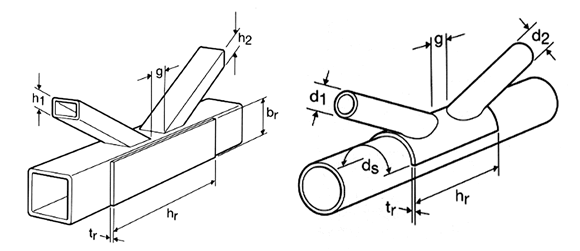
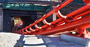
Figure 4.1: Tubes with external strengthening
A cheaper, easier to fabricate choice of member would be a smaller size, thicker walled section with joints that required no strengthening. Connection design rules and details are given in BS EN 1993-1-8.
Splices are necessary in long-span trusses for transportation: a 22 m length does not require any special arrangements for movement by road. Pipe-flange type joints are often used in truss booms and are efficient in compression. In tension, thick end plates may be required.
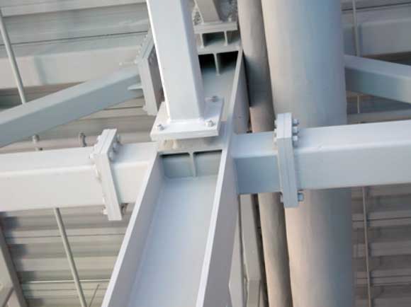
Figure 4.2: Thick end plate splices
Spade-type joints with cover plates can be connected to tubes by slotting them. Although introducing boom splices at mid span of a truss may not initially appear sensible, for a uniform load, the reduction in forces at third points for a parallel boom truss is only 11% so the difference in the splice arrangement is not likely to be large.
4.2 Open sections
Open section members are utilitarian and give more scope for bolted forms of connection. Booms can be oriented with webs vertical or horizontal with different benefits for each arrangement. Vertical webs with gusset plates welded on centreline result in a planar element through which forces can flow from member to member which may not require any strengthening.
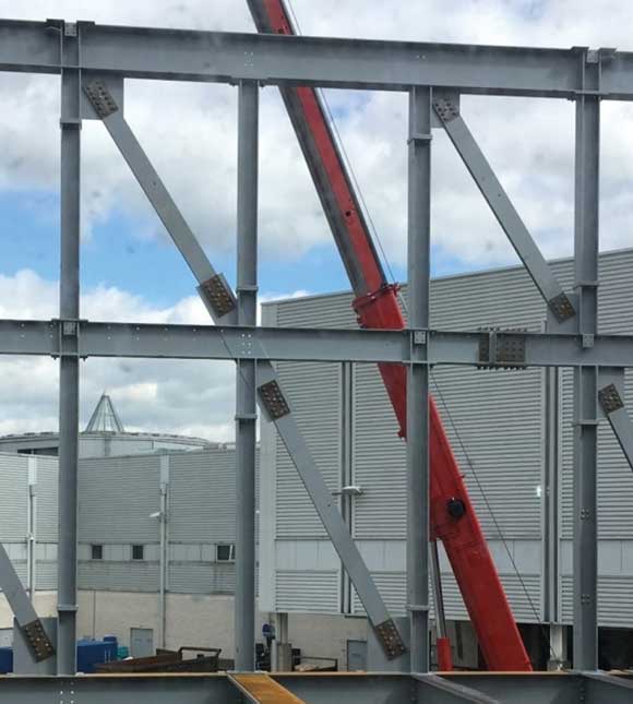
Figure 4.3: Thick end plate splices. Photo courtsey of H Young Structures Ltd
Vertical flanges provide a surface to which tension diagonals (flats or angles) can be welded in pairs with single compression members between. Top and bottom booms must be the same size however.
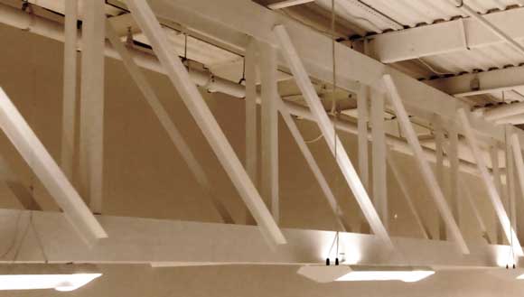
Figure 4.4: Vertical flanges
Open sections in compression can be orientated so that minor-axis buckling in the plane of the truss is restrained by secondary members provided for that purpose. The efficient use of material in the strut is traded off against the extra members and joints.
Gusset plate details are included in the SCI ‘Green Book’.
5 Compression boom restraints
A system of restraints to the compression boom of trusses is essential to their structural performance in a roof. Such restraints are usually provided by a system of in-plane bracing connected to purlins or specially provided restraint members. As discussed in the article on restraint to chords in (NSC, January 2017), careful consideration to the effectiveness of the connections between the truss booms and restraining members must be made. Clause 5.3.3 of BS EN 1993-1-1 gives guidance on the design of bracing systems used for restraint of truss compression flanges and indicates that such restraint forces are internal forces and are not transmitted to the building foundations.
Long-span light-weight roofs may be subject to wind uplift such that the bottom boom of the truss goes into compression. If this occurs, the bottom boom must also be adequately restrained to prevent buckling.
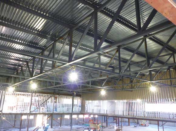
Figure 5.1: Top and bottom boom restraints
6 Conclusion
Trusses are a common and effective way of supporting long-span roofs in buildings. The variations in possible arrangement are very wide and the results range in appearance from delightful to utilitarian.