SSDA Awards
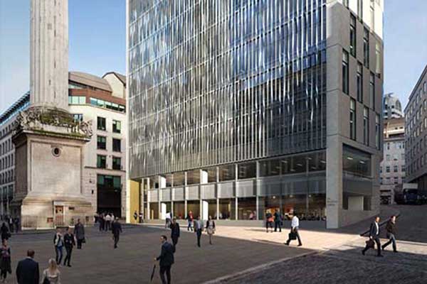
SSDA 2003 – 25 Gresham Street, London
25 Gresham Street is a 120,000 sq ft headquarters building providing 10 floors of column free office space. Developed by IVG Asticus Real Estate Ltd and now occupied by Lloyds TSB, it is situated on an island site in the City of London.
FACT FILE: 25 Gresham Street, London
Structural Engineer: Whitby Bird & Partners
Structural Contractor: Rowen Structures
Main Contractor: Exterior International
Client: Asticus (UK)
The site straddles the remains of a Roman fort and, in locations where foundation piles would otherwise have coincided with an archaeological deposit, the load paths were transferred using steel A-frames within the basement level.

The structure is designed as a braced frame with simply supported floor beams spanning between columns. Fabricated steel sections with an integrated service zone achieved 12m clear spans from the building perimeter to the core.
The central braced core provides lateral stability for transverse wind loads and the suspended south elevation. Vertical braced bays in the east and west stair cores provide additional resistance to torsion and out of balance loading on the hangers. Diaphragm action of the floor plates transmits lateral wind load from the perimeter cladding to the core.
The key architectural concept focuses on the relationship with the adjacent garden, originally the St John Zachary Churchyard. Accommodation is organised around an open sided south facing atrium overlooking the garden.
The atrium contains the principal vertical circulation, four glass lifts reached from a series of glass floored bridge decks and the scheme extends the garden with terraced planting beds climbing up the external face of the atrium. The imaginative use of structural steel enables the southern edge of the floors to be hung, thus avoiding any ground floor columns along the garden boundary. Steel vertical braced bays around the central service core resist the overturning moments induced by the inclined hangers. Plan bracing transfers the resultant push/pull horizontal forces at first and ninth floors from the hanger node points to the central core.

The diagonal tensile rod ties that provide support for the principal structure were assessed in a detailed fireengineering analysis to ascertain what effect an internal fire would have on the stability of the structure. The initial assessment was based on the ratio of energy input from the fire to the mass of the hanger available to absorb the energy.
To determine the performance of the hanger more accurately, assessors calculated the temperature of the environment to which a tension rod was likely to be exposed in a fire. Taking account of the thermal properties of the steel, the temperature of the fire and the duration of exposure, it was possible to calculate the peak temperature achieved by the hanger.
Temporary props supporting the first floor enabled the simultaneous construction of the suspended south bays with the main frame up to the hanger connection nodes at the ninth floor. Hydraulic jacks lifting the hangers transferred the load from the temporary props to the inclined hangers. Tension to the hangers was applied progressively, in pairs to control distortion sway on the structure. The measured movements were continually checked against the predicted theoretical values, determined from the detailed analysis of the frame and the tolerance allowances of the cladding assembly.
Judges’ Comments
This imaginative multi-storey steel framework has admirably accommodated the architecture, sunken garden and Roman archaeology in this City of London site. The attention that has been given to the relationship of this building with its external environment is clear to see, and very well done.
(Photograph courtesy of Edmund Sumner)