Projects and Features
Sir Harold Hillier Gardens Visitors’ Centre
A new single-story building with a cantilevered roof requiring precautions against wind uplift.
Client Hampshire County CouncilArchitects, Environmental Engineers and Quantity Surveyors Hampshire County Architects
Structural Engineers Price & Myers
Main Contractor Brazier Construction
Landscape Architect Colvin & Moggridge
Steelwork Contractor Allslade plc
The Sir Harold Hillier Gardens occupy a patch of rolling countryside to the north east of Romsey in Hampshire. Harold Hillier bought the 32 hectare estate in 1952 and before his death formed a charitable trust which is now administered by Hampshire County Council. Today the gardens and arboretum cover 72 hectares and contain one of the largest collections of hardy trees and shrubs in the world. In 2000 Hampshire County Council commissioned the County Council Architects to design a purpose-built visitors’ centre at the west entrance to the gardens to supplement the facilities provided in the original country house.

View of completed entrance
THE ARCHITECTURAL CONCEPT
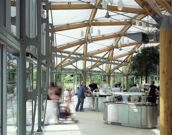
The visitors’ centre is composed of three buildings arranged in a U-shape around a simply landscaped courtyard which looks out down a gentle slope into the arboretum. They provide a restaurant, shop, offices and educational facilities. These pavilions sit under a single roof which covers the corner spaces between the buildings. The roof slopes down towards the central courtyard, which produces a high eaves level around the outer perimeter and creates a dramatic entrance to the gardens under the south west corner.

Computer drawing of diagonal steelwork.
THE BASIC STRUCTURE
The basic structure is a steel frame sitting on a concrete ground floor with deep mass concrete trench fill and pad footings founded in clay. The steel roof structure includes a mixture of trusses with hot-rolled UC section purlins. Cantilevered sections are bolted onto each end of the trusses to form eaves overhangs beyond the walls of the pavilions. The trusses sit on a central line of CHS columns and small RHS section posts within the taller outer wall of the pavilions. The main part of the roof deck is formed from composite insulated panels with a perimeter strip at the lower eaves in timber joist infill allowing a wide valley gutter to be formed. Where the roof oversails the pavilions at the corners, and at the ends of the side blocks the underside is clad in cedar boarding fixed to timber joist infill cut into a second layer of steel purlins.

Drawing of roof steel over entrance.
DESIGN DEVELOPMENT
From the start, the basic requirement was for a triangular section through the roof created by the top roof surface and two inclined planes at the soffit springing from a central line of columns. The desire was for as little internal structure as possible with unimpeded views towards the central courtyard. This suggested one internal line of columns with a cantilever section towards the central courtyard and a slim prop at the high point in the section, with lateral stability provided by connections to the central columns only.
A number of options for framing the roof were examined and it was decided that a diagrid of roof trusses would be the correct philosophical solution, as this was the only way to sensibly deal with the large corner cantilever. The original intention was also to expose the main roof steelwork by cutting the soffit finishes around it. However, consideration of finishes details led to a decision to lower the soffit and conceal the steelwork. This then made a diagrid less important for the straight sections of roof, so a cheaper orthogonal grid was adopted for these areas.
FINAL DESIGN
Final design is all about trying to distill the essence of the structure and make things cheap and easy to construct (there are of course many views on this). The central columns had to be circular as they sit within the main spaces so a 244mm diameter CHS was chosen, which gives a reasonable compromise between visual slenderness and bending strength. The architects wanted to see as thin a section at the eaves as possible. This put a premium on the depth of steelwork within the roof.
It was found to be possible to make everything from sections that were only 150mm deep. This was achieved within the roof by using all the variations of UB, UC and PFC sections in this depth to the exclusion of anything else excepting some small diameter tubes for in plan bracing. It was found that a 152 UC section would be adequate for the main members of the main trusses as long as the beams could act continuously. The trusses therefore use fully welded 152 UC 37 sections without any internal diagonal bracing which would have complicated the fabrication.
Lateral stability is provided in one direction by asymmetric portal frames and in the other direction by portal action in the four-posted corner frames. The main column bases were also detailed to give some fixity to assist in reducing lateral deflections at roof level in order to reduce lateral drift as much as possible to limit any effects on the glazed ends of the pavilions. The site is in open country and fairly exposed to the wind. The roof crosssection has certain similarities to an aircraft wing and produces appreciable uplift on the leading edge combined with a tendency to overturn due to down drag on the trailing edge. The open corners and overhanging ends are particularly vulnerable to this effect and needed some quite large lumps of concrete in the ground to hold them down.

View through middle of completed building.

Sketch of main truss connection.
STEELWORK DETAILING
It was felt to be beneficial for the trusses to be fully prefabricated welded units. The key question was then how the trusses should be connected to the main CHS columns to give full moment resistance. Bolted connections would have been bulky and probably have projected into the soffit finishes zone which was tight up to the underside of the trusses. A grouted spigot-and-sleeve connection which allowed the trusses to be dropped over the top of the CHS columns was therefore developed, and it produced a very robust connection. This provided the desired appearance but proved less easy to erect than a bolted structure.
Slightly different detailing was needed for the two corners of the U-shaped roof where the four CHS columns have to stabilise the 9m cantilever. Trusses fabricated from 152 UC sections are not quite strong or stiff enough in this situation, so a 10mm web plate was introduced between the top and bottom flanges which are formed from pairs of 150 x 75 mm parallel flange channel sections. Flitch plates are used to stabilise the external glazing panels. These can be problematic if the design responsibility is not clear and the tolerance issues are not addressed and understood by both the designers and the installers. In this instance, top and bottom connections which allowed a lot of latitude in the final position of the flitch plate, were designed to make sure that the connections did not foul the wall panels. It was then comparatively simple for the wall panel manufacturers to work with the engineers and the steelwork contractor to make sure that everything was co-ordinated and went together smoothly on site.
The steelwork is all grade S275. The roof geometry produces some complicated connections with subtle slopes and shapes within the corner diagrids which would have been difficult to get right through hand drawing and calculation alone. We therefore specified that the steelwork contractor had to have a 3D modelling capability. The computer-aided drawing and fabrication process generally worked well, and certainly having 3D printouts of some of the fabrication drawings was invaluable to us as designers.
CONTRACT AND PROGRAMME
The design team worked with the main contractor in a partnering arrangement. The steelwork contractor was appointed in December 2001 and completed the main steelwork in the summer of 2002. The visitors’ centre opened to the public in June 2003.
Paul Batty, associate engineer at Price & Myers