Technical
AD 510: P281 worked example of beams curved on plan
SCI publication P281 was published in 2001 covering the design of curved steel members, in accordance with BS 5950. It is clear that this guide is still used, as SCI receive occasional questions. The most common question, repeated recently, concerns example 6 which covers the verification of a universal beam curved on plan.
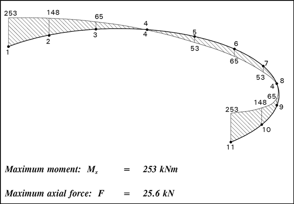
The design process starts by applying the vertical load to the curved beam, which produces a bending moment diagram as reproduced from the example:
Designers following the example generally question how the axial force of 25.6 kN shown below the bending moment diagram has been determined. The unfortunate answer is that the determination of this axial force should have come later in the process – the value is correct, but the location of the text causes confusion.
The bending moment as shown above is converted into axial forces in the flanges, simply by dividing the moment by the lever arm between the flanges. If the top flange is considered, the flange force is tension near the supports varying to compression at the furthest part of the curved member.
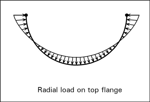
Since the top flange is curved on plan, the axial force just calculated has a radial component of varying intensity – the component is “inward” adjacent to the supports, and “outward” when the flange force is compression.
This varying radial force is shown below (again taken from P281).
The next step is to analyse the curved member again, with the loading shown above. This produces a bending moment (given as 149 kNm in the example) and an axial force. The value of this axial force is the 25.6 kN, which has been quoted at the earlier location in the example.
The process is described in steps in section 8.5.4. As there are two forces “F”, it may be helpful to identify them separately. In Steps 1 and 2, the equivalent flange force – which leads to the radial components, might be defined as F₁.
Steps 3 and 4 cover the analysis of the member subject to the radial loads, which produces an axial load which might be defined as F₂. In this example, F₂ = 25.6 kN. Referencing this force within Steps 1 and 2 of the numerical example has led to the confusion identified earlier in the Note.
Contact: David Brown
Telephone: 01344 636555
Email: advisory@steel-sci.com


