Technical
New tests demonstrate superior performance of steel-framed floors
Recent vibration tests on composite floors in steel-framed hospital buildings have confirmed that the real performance of composite floors is superior to that suggested by a floor comparison study that was published by the Concrete Centre. Dr Stephen Hicks, SCI Manager for Building Engineering reports
Over the last eight years, the SCI has been involved in UK and European-sponsored research on floor vibrations. This has resulted in a database of measurements on steel-framed floors being compiled, together with the development of predictive tools that have been calibrated against these measurements. This article presents the results of recent vibration tests on composite floors in steel framed hospital buildings. It was discovered that all of the steel-framed floors out-performed the NHS requirements for operating theatres by a factor of between 2 and 4. These measurements are in stark contrast to results presented by the Concrete Centre in 2004, which were based on simplistic comparisons of concrete and steel floors using only predictive methods.
Vibration tests on composite floors
Attempts have recently been made to compare the response factor performance of different floor systems (Concrete Quarterly, Winter 2004)(1). This study was based on applying predictive techniques to a single simple floor and comparing the theoretical effect of different construction methods on response factor values. The floor construction methods that were considered were RC flat slab, post-tensioned RC flat slab, a conventional steel and concrete composite floor and the Slimdek system. Although this approach facilitates comparisons, it has the following disadvantages:
- The simple floor is not representative of floor layouts commonly used in practice
- No allowance is made for the position of the walking activity in relation to areas where a particular response factor is required (e.g., operating theatres in hospital buildings only represent a small proportion of the total floor area)
- As the performance of each floor is based only on predictions, the comparisons are strongly affected by accuracy of these predictive techniques and the assumptions used in the calculations
So that fairer comparisons can be made, the SCI arranged to test a number of composite steel-framed hospital floors recently constructed and designed according to the latest guidelines.
Vibration testing requires specialised equipment and sophisticated data processing. The key items of equipment needed are a means of exciting the floor in a controlled way and accelerometers to measure the floor vibrations. Post-processing makes use of methods based on the Fourier transform, which converts a signal measured as a function of time to one in terms of frequency. Two types of excitation method are commonly used: impulsive and continuous forcing.
Impulsive methods
Impulsive methods such as impact hammers are the most transportable, and are usually adequate for simple structures. The hammer is fitted with a soft tip and a force transducer, so that when it is struck it puts a known amount of energy into the structure over a wide range of frequencies. An alternative form of impulsive excitation is the heel drop test, which consists of a single person raising themselves on the balls of their feet, and suddenly dropping on to their heels (in the past, this simple loading function has been used within some design guides to assess the acceptability of floors). However, a long-standing problem with this approach has been that the input force is not measured, and may vary from test to test. Some researchers have recently remedied this by developing an instrumented heel-drop test, where the heel-drop is executed on top of a slim, purpose-built load cell.
Continuous forcing methods
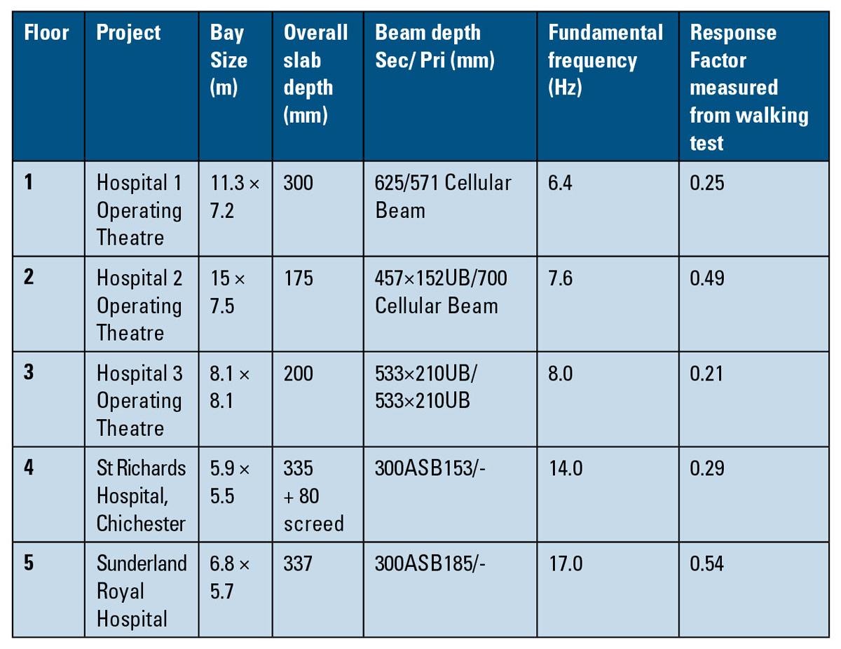
Table 1. Response factors used to specify satisfactory magnitudes of building vibration with respect to human response
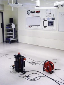
Impulsive tests sometimes have difficulty distinguishing between closely spaced natural frequencies. The existence of several very close modes of vibration is quite common in floors, which often have several bays of similar stiffness in each span direction. In such cases, better quality data may be obtained by providing a continuous forcing input to the floor. A novel multi-shaker floor excitation system developed at the University of Sheffield was used on two of the floors presented in this article (Floor 4 and Floor 5 in Table 1). This new and unique modal testing system is based on high-quality frequency response function (FRF) measurement and curve-fitting. It enables adequate distribution of vibration energy, which is the key problem when testing large-scale civil engineering structures; this leads to considerably improved reliability in the measurements. An image of one of the shakers is shown in Figure 1.
As well as determining the damping and frequency, the mode shapes can also be evaluated from testing. This is achieved by moving the excitation source or the accelerometer to a predefined set of grid points on the floor and monitoring the response. On Floor 4, accelerometer readings were taken at 26 points.
Walking tests
Once the modal properties of the floor have been established, the response of the floor can be measured directly from walking tests using a variety of paths and pace frequencies. These measurements can then be compared to published acceptability guidelines to produce in situ ‘response factors’ (or ‘multiplying factors’) for the floor.
The aim of walking tests is to ascertain the worst (design) case for the response of floors in service. Through a research programme supported by the European Commission(2) it was found from measurements that the average frequency for people engaged in walking activities is 2.0Hz. To take account of variations in service, the walking tests presented in Table 1 were conducted at frequencies of between 1.5–2.5Hz (a range equivalent to three standard deviations about the mean value of 2.0Hz). The pace frequency was controlled by walking in time to a beat generated by a portable computer or a metronome.
The response factor values presented in Table 1 are based on the highest one-second RMS acceleration recorded from walking tests (equivalent to a ‘slow’ integration time constant according to ISO 2631-1: 1997)(8)
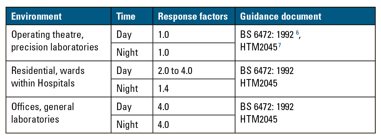
Table 2: Response factors used to specify satisfactory magnitudes of building vibration with respect to human response
As can be seen from Table 1, all the floors easily satisfied the appropriate performance standards shown in Table 2 for an operating theatre environment, out-performing the HTM 2045(7) requirements by a factor of between 2 and 4. Since acceleration response is inversely proportional to mass, it would indicate that significant reductions to the slab thicknesses could have been made in these cases. For example, for Hospital 4, the 80 mm screed could have been eliminated and the slab to the Slimdek® floor could theoretically have been reduced to 240 mm (though this a thickness that could not be practicably achieved, owing to the depth of the current Asymmetric Slimflor® Beam (ASB) range).
Measurement and design of vibration response
The basis of measuring and designing for vibration response was covered in an earlier article (The real performance of modern steel-framed floors, NSC June 2005). For convenience, the main points are repeated here.
Vibration magnitude is normally measured in terms of acceleration. To express the severity of human exposure to vibration, a root-mean-square value is used. The perception of vibration depends on the direction of incidence to the human body, and to account for this most modern standards used the ‘basicentric’ co-ordinate system in which the z-axis corresponds to the human spine.
Traditionally, the design of floors for occupant-induced vibrations has been based on providing a minimum natural frequency (which depends on the ratio of the floor stiffness to its mass).
However, resonant accelerations can still arise from components of the walking activity, and natural frequency limits do not give any indication of the acceleration response. As a consequence, it is now more common for designers make predictions of the RMS accelerations expected in service.
Guidance for designing steel-framed floors for vibrations is given in SCI publication 076(3), which is supplemented by three SCI Advisory Desk Notes(4). Specific guidance for uniform floor layouts and grids common in hospital buildings has recently been provided in SCI publication 331(5). These publications permit designers to make an estimate of the expected response factor by using hand calculations.
Alternatively, as numerical modelling of floors becomes commonplace, finite element analysis techniques are sometimes employed. The SCI has developed a software prediction tool that may be used to estimate the response factor for a floor through a research programme supported by the European Commission(2). This tool has been calibrated against a database of measurements that have been recorded on real floors over the last eight years.
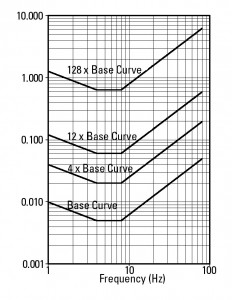
The evaluation of the exposure of humans to vibrations within buildings is covered by BS 6472: 1992(6). Limits of satisfactory vibration magnitude are expressed in relation to a ‘base curve’ and a series of multiplying factors (also known as ‘response factors’). The base curve for vibrations in the z-axis direction, together with a range of typical factored curves, is shown in Figure 2. Each line in Figure 2 represents a constant level of human reaction, known as an isoperceptibility line. The area above a line corresponds to an unacceptable human reaction. Maximum response factors currently recommended for the UK are given in Table 2.
Conclusions
Measurements on five hospital floors using conventional composite construction and Slimdek show that steel-framed floors are easily capable of achieving the strict vibration requirements for operating theatres given in HTM 2045. Furthermore, the implications for Slimdek® floors in hospital buildings is that they do not have to be designed any differently from floors that are commonly used in buildings for the commercial sector.
These measurements also show the dangers of making simplistic comparisons using only predictive methods which, in a previous study(1), inferred that steel-framed floors have an inherent difficulty in achieving hospital performance standards. In that study it was suggested that a Slimdek® floor would need to be significantly deeper than floors in the commercial sector to achieve a response factor of 1.0 (equivalent to a slab depth of 420 mm plus a 50 mm screed). Conversely, in the measurements presented here, a response factor of only 0.29 was achieved on a floor that was 14% thinner.
References
(1) Minson, A: ‘A firm footing for good vibrations’, Concrete Quarterly, Winter 2004
(2) Generalisation of criteria for floor vibrations for industrial, office, residential and public buildings and gymnastic halls, European Coal and Steel Community (ECSC) -Steel Programme, 7210-PR/314
(3) Wyatt, T.A.: ‘Design Guide on the Vibration of Floors’, SCI Publication 076, Ascot, Steel Construction Institute, 1989
(4) AD253, AD254 and AD256 Design considerations for the vibrations of floors, www.steelbiz.org
(5) Hicks, S.J. & Devine, P.J: ‘Design guide on the Vibration of Floors in Hospitals’, SCI Publication 331, Ascot, Steel Construction Institute, 2004
(6) BS 6472 Evaluation of human exposure to vibration in buildings (1 Hz to 80 Hz), London, British Standards Institution, 1992
(7) Health Technical Memorandum 2045: Acoustics: Design considerations, London, HMSO, 1996
(8) ISO 2631-1. Mechanical vibration and shock – Evaluation of human exposure to whole-body vibration: Part 1: General requirements, International Organisation for Standardization, Geneva, 1997


