50 & 20 Years Ago
Manchester Road Bridge
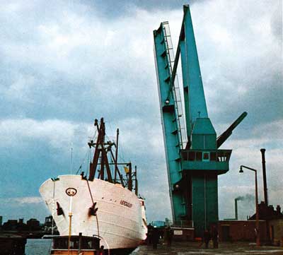
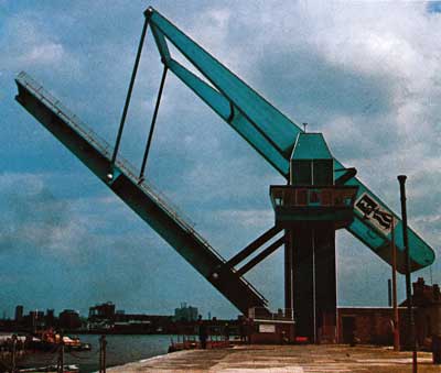
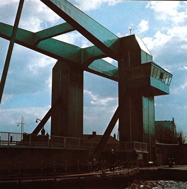 Using a principle of mechanics centuries old this new bridge has been described as a ‘shaduf in steel’. This design however makes use of the latest technology to achieve operating efficiency with considerable elegance in appearance. Mr. R. E. West CEng, MICE, of the Engineering Dept, Port of London Authority here briefly describes the structure which was opened in 1969.
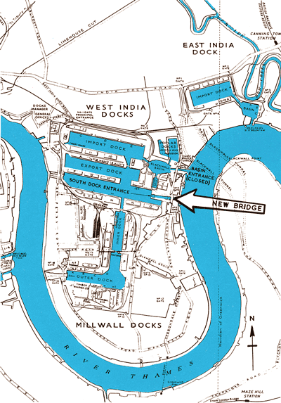
 Until 1969 the South Dock Entrance of the India and Millwall Docks group was spanned by a double leaf cantilever bridge of Schertzer pattern. This bridge carried Manchester Road which is part of the perimeter road around the Isle of Dogs. However, after forty years service the bridge was in need of repair, partly from deterioration of the bearing girders, partly from damage caused by ships colliding with the footway and main girders and also because the motors and switchgear had reached the end of their useful lives. Various design studies were completed to examine the economics of repairing the existing structure or building a new bridge and the cost difference was so little that the decision was made to go ahead with a new installation at a cost of about £250,000. The existence of massive concrete foundation blocks for the double leaf bridge influenced the choice of structure and enabled considerable economy to be made in the civil works.
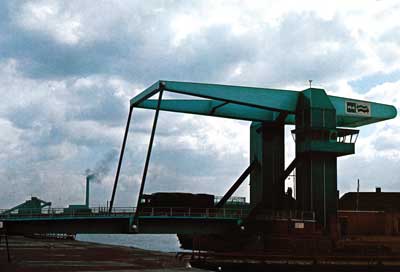
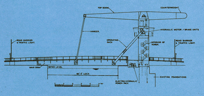
The selected design is of a counterbalanced drawbridge type similar to those traditional to Holland. However, Manchester Road bridge is on a larger scale and is believed to be the biggest bridge of its type anywhere. The line of the road has been maintained and its new slightly elevated profile has been graded down to meet the existing levels. Manoeuvring a ship through a lock entrance is not easy, particularly when there are strong tides or high winds. For this reason the towers have been sited on the south side of the entrance as experience has shown this to be the less vulnerable position. The bridge span of 110ft is greater than the lock entrance so that when it is raised sufficient width remains on the quay to work ships through. The roadway is 25ft wide, thus providing two lanes of traffic and there are two 7ft 6in footways. ‘Verynyl’ PVC tiles are bonded to the steel deck to provide the road surface and crash barriers protect pedestrians from vehicular traffic.
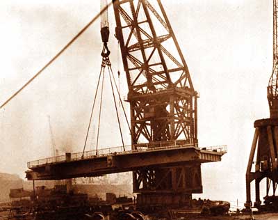
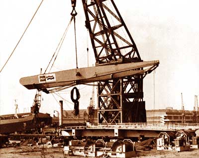
The particular type of bridge consists of a few large components and these were assembled by site welding prefabricated sections together in an erection yard at the lock side. The towers are held down by anchor rods which were grouted into holes drilled into the existing concrete foundations. All parts of the bridge were raised to the open position within a few hours of erection so that no obstruction was caused to ships using the dock.
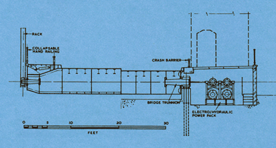
The superstructure is welded throughout and in general is fabricated from steel to BS 2762 ‘Notch Ductile Steel for General Structural Purposes’. Since the racks operate on the sides of the deck structure they impose considerable torsional loads which are efficiently resisted by the closed cellular structure. Local point loads are resisted by Universal Beam stringers while the hangar, rack and main trunnions are supported by integral transverse boxes. The orthropic road deck is designed to BS 153 HA loading plus 45 one-ton units of HB. The towers are 12ft square and withstand all loads from the operating racks as well as supporting the top booms and counterweights.
The lifting racks are activated by driving pinions which are driven by hydraulic pumps powered by two 70 HP electric motors. The combined pump and motors are situated immediately behind the main trunnions on which a cam is mounted so that the delivery of the pumps is always related to the inclination of the deck, thus ensuring complete control of its angular movement and dispensing with the more usual electric limits and inching motors. The deck is raised or lowered in approximately one minute.
Erection of the superstructure was effected rapidly as the components were few in number. To lift them into position use was made of the PLA’s 200 ton lifting crane.
In order to eliminate the risk of any accidents operation of the bridge is manually controlled by remote push buttons (all controls are electrically interlocked to ensure that they are operated in the correct sequence). The control cabin is large in area and has a clear view of both the road and the lock. It will be possible in the future to operate all lock gates and sluices from this position though this is not done at present.
Maintenance of the bridge is the responsibility of the PLA and to keep costs down care has been taken to ensure that work can be carried out as easily as possible. To this end the external surfaces of the superstructure are easy to paint while bearings should need no more than occasional packing with grease. The pump/motor sets are duplicated so that the bridge can be operated while one set is being serviced.
The bridge is a good example of the unique properties of steel, no other material being suitable for the purpose.
Main contractors for the superstructure
Sir William Arrol & Co Ltd
Sub-contractors for the operating machinery
MacTaggart Scott Ltd
Contractors for the civil works
John Mowlem & Co Ltd
Design and erection supervision
Engineering department of the Port of London Authority (Chief Engineer J. F. Stanbury C.Eng, FICE)


