Projects and Features
Hot and cold
The complex steel design involving two large stacked column-free areas
A swimming pool and an ice rink are being built within one large steel-framed structure in Romford, presenting several challenges.
FACT FILE
Romford Ice Rink and Swimming Pool
Main client: London Borough of Havering
Architect: Saunders Boston
Main contractor: Willmott Dixon
Structural engineer: AKS Ward
Steelwork contractor: Billington Structures
Steel tonnage: 1,200tConstructing two large column-free spaces stacked on top of each other may be a challenge in itself, but if one contains a heated swimming pool and the other an ice rink, all of a sudden a whole host of unique issues concerning temperature and isolation arise.
This is precisely what Willmott Dixon is facing at Romford where, in order to fit all of the required amenities into a tight footprint, an ice rink is being built above a swimming pool at a new leisure centre, something that is said to have only been done once before in the UK.
Working on behalf of the London Borough of Havering, the £28M flagship Romford Ice Rink and Swimming Pool complex will deliver an eight-lane competition swimming pool, fitness suite and 56m x 26m ice rink in the heart of the town centre.
The council says the long-planned development will assist the cultural renewal of Romford and will make a huge impact on the local economy by attracting new inward investment.
The new rink will also provide a home for the local ice hockey team, London Raiders, who relocated to Lea Valley when Romford’s former ice rink closed in 2013. The team plans to take up residence in time for the 2018/19 season.
Commenting on the project’s unique features, Willmott Dixon Project Manager Simon Cook says: “The temperature differential between a hot pool and a freezing ice rink has made this building particularly challenging to design and build.”
The difference in temperature creates the potential for surface condensation due to warm, moist air hitting a very cold slab above the pool.
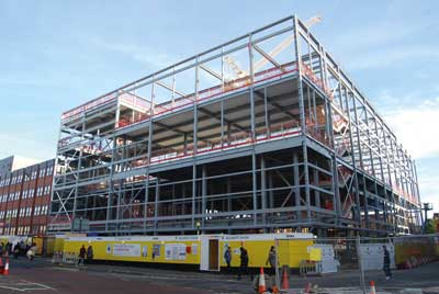
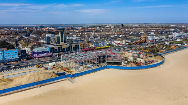
The project is located in the heart of Romford town centre
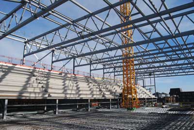
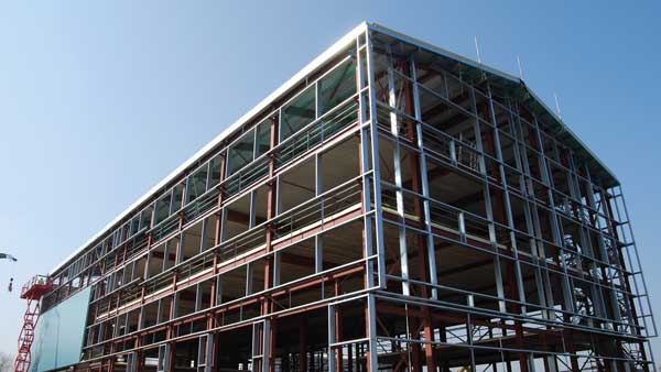
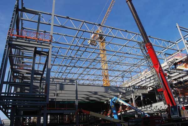
The upper-level ice rink under construction
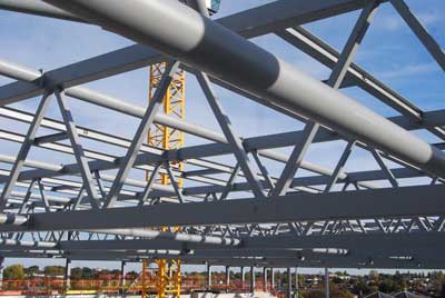
Roof trusses spanning the ice rink
As most ice rinks are built on the ground this is not an everyday problem, but the solution was relatively straightforward. A thick layer of carefully detailed insulation was installed below the 200mm thick composite slab. This protected the network of ice rink cooling pipes encased in the super-flat concrete slab which had to be constructed to a surface tolerance of +/- 3mm. Below this, steelwork supporting metal decking was punctured with 300mm diameter holes through the webs to increase air circulation.
As well as isolating the ice rink from the pool, the other big challenge was creating the large spans for each of these two distinct facilities.
“Due to the extensive spans we required, and because of the unique challenges of constructing an ice rink over a swimming pool, our preferred approach was to use a steel frame solution,” explains Saunders Boston Architects Director Nathan Swift.
“Steel was the obvious choice to accommodate the 25m-long span competition pool, an array of water balancing tanks, a learner pool and the ice rink’s 42m-long span,” agrees AKS Ward Engineer Sophie Onoufriou.
“Both vertical and horizontal deflections of the structure were also very tight and difficult to achieve due to the large open spaces and double height voids. Locating steel cross bracing at the right places was a challenge.”
Spanning the ground floor swimming pool are a series of 35m-long by 1.55m-deep plate girders. Supported by perimeter columns and one internal column line, the girders create two spans, one 25m-wide zone for the pool and another 10m-wide zone primarily taken up by changing rooms.
Because of the high humidity levels expected inside the pool area, the girders and their supporting columns are protected for the chlorinated environment by means of a high quality paint system suitable for a C4 environment.
The structure’s main columns are spaced at 6m centres. However, due to the length of the required span and the loads from the ice rink, the plate girders are spaced at 3m centres with intermediate girders located in between each column spacing.
Steelwork contractor Billington Structures delivered these 35m-long girders to site in three sections. Two sections were bolted together on the ground to form one long member, which was then lifted into place using a mobile crane. The third section was lifted separately and the final splice completed mid-air.
Creating the roof of the leisure centre and the large 42m-long span over the ice rink is a series of trusses. These were also brought to site in three sections and erected in a similar fashion.
The ice rink will have spectator terrace seating on either side, with the highest bank of eight tiers on the western elevation of the facility formed with steel rakers bolted to the main steel frame supporting precast seating units.
Exerting more loads on to the project’s steelwork, and another reason why the plate girders are spaced at 3m centres, the ice rink’s floor will also have to support an 8t ice surfacing machine.
This vehicle cleans and smooths the surface of the ice sheet and a rink operator will generally use its machine a couple of times a day.
A steel-framed storage space beside the terrace seating has been erected, as well as a large ice pit where ice shavings are dropped into warm water before being drained away.
Summing up, Mr Cook says the project’s other main challenge has been the logistics of working on such a tight site.
“Prior to steelwork starting on-site we piled the site and then excavated the pool, as this would have been very difficult to do once the frame was up.”
“This means once the steelwork programme is nearing completion we can then start concreting the pool and ground floor slabs, working inside the footprint and around the erected columns.”
Romford Ice Rink and Swimming Pool is due to complete in January 2018.
 Splice connections
David Brown of the SCI discusses splices in long-span members.
The long spans at the Romford leisure centre meant that splices were required in both the plate girders supporting the ice rink and in the trusses above the rink. Generally, slip in splices must be avoided, but this was particularly important in the plate girders supporting the ice rink where deflection was tightly controlled. Any slip in the connection could lead to deflection making the rink unusable due to cracked ice. Preloaded assemblies were used to prevent slip. Decking was supported on the top flange of the girders, so external flange plates could not be used – countersunk bolts were specified and internal flange plates. BS EN 1993-1-8 has particular rules for the design of splices in beams, in clause 6.2.7.1(16). This clause requires that the web connection must be designed to transmit the proportion of moment carried by the web – even if it has been assumed that the flanges alone carry the moment. The assumption that all the moment is carried by the flanges – and the flange plates and bolts designed for the forces – has been UK practice for many years, so the Eurocode represents a significant change. The design resistance of preloaded assemblies is straightforward, but depends on the slip factor (coefficient of friction) between the mating (‘faying’) surfaces. The key requirement is to ensure that the faying surfaces meet the assumptions made in design – inadvertent painting of surfaces specified as bare steel in the connection design will lead to a significant reduction in the slip factor.
The roof trusses at the leisure centre are formed from hollow sections, fabricated into three sections and bolted together on-site. In any truss, the strength of the joints is a key design requirement so that expensive strengthening is avoided by judicious selection of members and geometry. Checking joint resistance in accordance with BS EN 1993-1-8 can be laborious, but software is freely available from Tata Steel. Splices between hollow sections are often achieved by end plate details, sometimes called ‘pipe flange’ connections, where end plates are extended outside the hollow section and bolted together. This detail was used at Romford for both truss chords and internal members at the splice locations.
Romford leisure centre is particularly notable because there is a comprehensive time lapse archive of the construction, at www.romford.photosentinel.com.au. Plate girders can be seen bolted together on the ground and assembled on 4 October, pm. A truss can be seen being assembled and erected on 13 October, pm. There are three high-quality photos taken every hour which provide a fascinating resource.