Projects and Features
Fuel efficiency
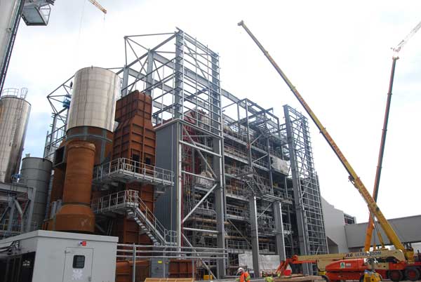
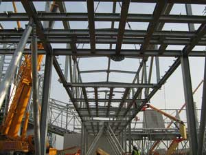
Steelwork being erected around the turbine equipment
Steelwork’s flexibility and economy of design are major pluses when building an energy centre around multiple equipment installations.
FACT FILE
Brigg Renewable Energy Plant
Client: Fichtner
Architect: Ramboll
Main contractor: BWSC
Structural engineer: Ramboll
Steelwork contractor: Caunton Engineering
Steel tonnage: 1,430tFinding cleaner and more environmentally friendly ways of generating energy is one of the most important issues of the day.
It has seen many local authorities investing in renewable energy plants where either household waste or another renewable commodity is used as fuel.
One of the latest projects of this ilk is a new 40MW renewable energy plant under construction at Brigg, Lincolnshire. It will generate enough electricity to power 70,000 homes using straw and woodchip as a sustainable fuel source. It is claimed this will save 300,000t of carbon dioxide emissions per annum.
The Brigg Renewable Energy Plant is scheduled for commissioning in early 2016 and is expected to create 30 jobs during operations and 50 jobs in fuel supply.
Being built on a site formerly occupied by a sugar factory, the straw-fuelled plant will use more than 240,000t of wheat straw feedstock annually, which will be sourced from producers within a 50-mile radius, while woodchip will be used as an auxiliary fuel.
Overall the facility comprises a turbine building and attached office block and boiler hall, two straw storage barns and woodchip shed. All of these structures are steel-framed, as are a number of enclosed bridges linking the main buildings and housing conveyor belts.
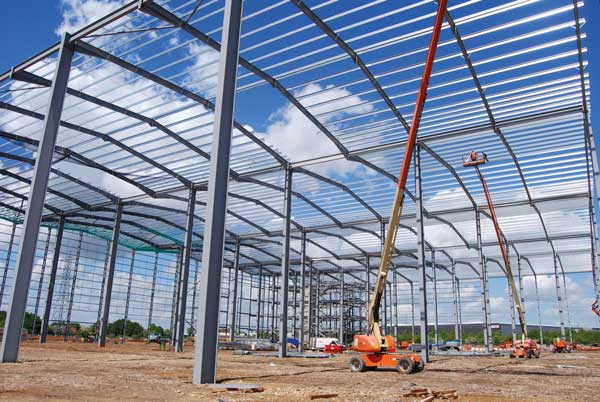
The long spans inside one of the straw barns
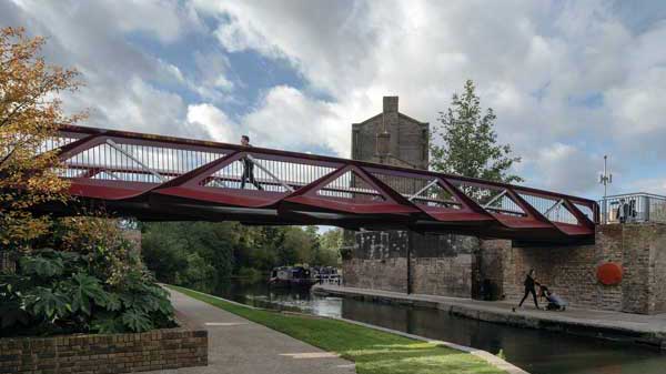
A conveyor bridge under construction
“Steel is the most efficient way of designing this sort of energy centre as it allows the flexibility to construct the tall buildings quickly and economically,” explains Ramboll Senior Project Manager, Agust Asgrimsson.
The project is on a fast-track construction programme and in order to keep the job on schedule, the steel frames for the boiler hall and turbine building had to be erected around equipment installation
“Much of the project’s steelwork was designed to include temporary works, so that it could be partially erected around equipment installation,” adds Mr Asgrimsson. “The boiler hall for instance was initially erected without one façade and its roof so the boiler could be lifted into place during a break in the steel erection process.”
Steelwork contractor Caunton Engineering erected the boiler hall with columns brought to site in 10m lengths. This allowed the structure to be initially erected to a height of 20m, with only three façades in place as the fourth façade was left out to allow access for other trades.
Once the boiler equipment was in place the remainder of the structure, including the roof, was erected and the temporary bracing removed.
The boiler house is a large 30m-high braced structure, designed with a series of temporary wind girders positioned around the perimeter. With a combined weight of 10t, these temporary members were only removed once the main boiler equipment was in place.
The roof consists of five 32m-long trusses, weighing 10t each that had to be assembled on the ground from two sections before being lifted into place.
The adjacent turbine hall was designed in a similar way, with temporary bracing and props, allowing openings to be left in the steel frame.
“Using steel allowed us to design frames that could be erected quickly and in conjunction with other trades,” says Mr Asgrimsson.
The boiler hall, turbine building and the offices form one large steel frame and were erected in a sequential manner. Each of the three zones is however separated by a fire-protected row of columns and wall.
The first steel buildings to be erected were straw barn (one) and the boiler building. The concrete slab for the second straw barn was used as the steel assembly area, as erection of this frame only commenced once the boiler equipment had been installed.
“When we erected these two structures it was quite early in the overall construction programme and we had the area to ourselves,” says Caunton Engineering Site Manager Robert Aitman. “Once they were finished we left site until most of the turbine and boiler equipment had been installed.”
The two straw barns are identical braced frames that are structurally independent but are linked via a conveyor system that feeds straw to the boiler house.
The sheds will receive deliveries of straw bales, and have two 20m spans and a single line of internal columns – ideal for storage and vehicle movements.
The completed straw barns were then used as storage areas for weather sensitive construction materials for other parts of the works. Some parts of this structural frames had already been constructed, but one elevation and the roof were completed while the boiler was being commissioned.
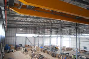
Each of the straw barns has parallel roof level crane rails to support two overhead cranes. These units will work 24-hours a day and will consequently exert considerable loadings into the steel frames. Stiffness of the frame was consequently important to avoid any movement. Meanwhile, to avoid fatigue the barns’ frames have been designed to Execution Class 3.
The coordination of the steelwork programme around other activities was also a key part of the conveyor bridge erection. Once they leave the straw barns, two conveyors converge into one and feed into a sorting zone and then the boiler.
The conveyors are housed with enclosed bridges and span a number of roads and passageways. To keep one of these main thoroughfares open for the other construction trades, Caunton assembled one large 35m-long bridge section onsite and, using a 160t-capacity mobile crane, lifted it into place in one single weekend operation.
“As this bridge section spans the busiest and most used thoroughfare within the site, we were able to minimise any disruption by working in this way,” sums up Mr Aitman.
Summing up the project the client BNLL say: “We are very happy with the intuitive way that this construction has been designed. The co-operation between the parties recognising others needs has certainly paid dividends thus far with respect to achieving an early completion.”
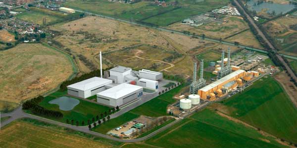
CGI of the completed scheme
The Process
The straw fuel for the plant will be delivered on flat bed trailers and unloaded into one of the two straw barns.
Each straw barn is capable of holding straw bales sufficient for 36 hours of operation. The straw is transferred to be burnt in the boiler to produce high-pressure, high-temperature steam which drives the steam turbine to generate electricity.
The steam passing through the turbine is condensed back into water, with the help of an air-cooled condenser, for reuse in the boiler.
The hot combustion gases generated in the process pass through a complete cleaning system before being released through the chimney stack and the ash produced due to the combustion of straw is recycled for fertiliser.
The power plant is designed for continuous operation for base load power generation except one annual shutdown for inspection and repair.