50 & 20 Years Ago
Footbridges
From Building with Steel, August 1973
In the days when early Renaissance artists were required mainly to paint altar pieces they carried out many of their experiments in the small predella panels which were not so restricted in treatment by the clerics as the main pictures above. Perhaps it is stretching the analogy too far to suggest that footbridge designers have similar freedom from restrictions bound as they are to follow the dictates of BS and CP. Nevertheless the examples featured in these pages do exhibit a freedom from the conventional approach that is often pleasing in its results and sometimes appears a little more adventurous than is found in most larger structures.
But it would be wrong to suggest that all footbridge design is unconventional or that it should be. Clearly each structural solution is developed from the conditions laid down in the brief and often the most important of these is cost. When this is so a conventional approach is often the most easily justified and in any case might well be the most appropriate when measured against the other criteria. With our growing concern for the environment we are becoming much more conscious of the design and placing of all man-made objects and it is evident from these pages that well designed steel footbridges can often enhance rather than detract from their surroundings.
Maiden Castle
Durham
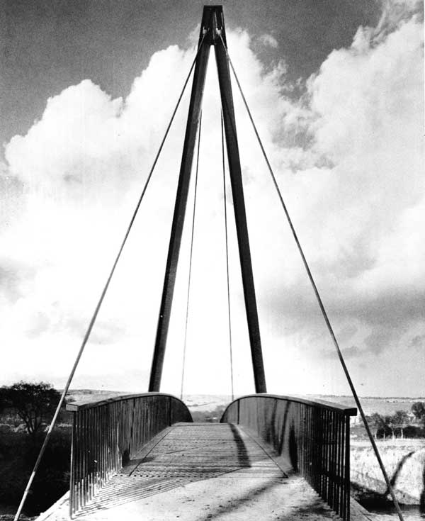
A one-mile journey has been eliminated by this new 188ft span bridge linking the playing fields and changing facilities at Maiden Castle Sports Hall. Although primarily for pedestrians, vehicles and maintenance equipment can cross the bridge. The cable-stayed structure is asymmetrical supported from an A frame on the Maiden Castle side as the opposite bank could not carry heavy erection equipment. Protective bunds about 40ft from the banks necessitated a longer span than the river required. Ample clearance has been provided for severe flood conditions. Steel was chosen for economy and ease of construction.
Owners: University of Durham
Engineers: Ove Arup & Partners
Steelwork Contractors: Robert Frazer & Sons Ltd
Arley, Worcestershire
over River Severn
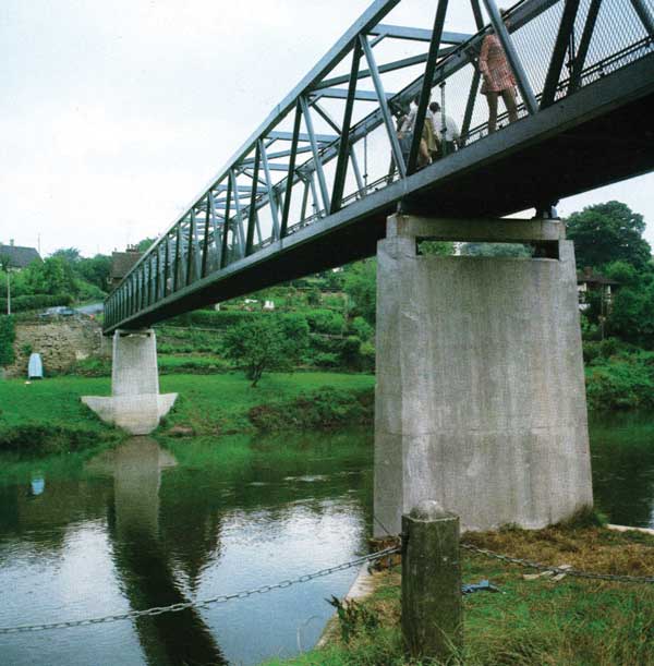
This 270ft long continuous bridge is constructed from structural hollow sections with a mild steel plate deck. The centre span is 154ft and the side spans are each 57ft 6in while the width is 6ft. It has been designed for crowd loading and prior to opening was subjected to a test from tractors carrying sand. The structure is painted in two shades of green to blend with the natural beauty of this delightful stretch of the Severn between Bewdley and Bridgnorth.
Client and Engineers: Worcestershire County Council (W.R. Thompson, FICE, F Inst HE, County Surveyor and Bridgemaster)
Contractor: Worcestershire County Council
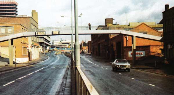
Leicester
Over Charles Street
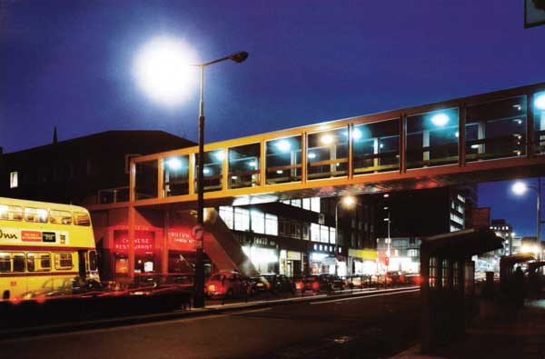
This bridge links a large city centre shopping and entertainment complex at Haymarket, Leicester to an important access area by crossing busy Charles Street which has dual 3-lane carriageways. The brief from the city engineer laid great emphasis on aesthetics. For slimness and lightness steelwork was selected and of the alternatives Vierendeel girder was favoured. The girders are 2·75m deep and 22·6m long and are stabilized with roof and floor diaphragms. The girders are made of high-yield steel rectangular hollow sections. Erection took place during one Sunday during which Charles Street was closed. The floor deck consists of a troughed steel sheet which was laid as soon as possible to enable concreting and finishing to take place over the opened road. Access to and from the bridge is by escalators at one end while at the city centre the level matches the bridge deck.
Client: City of Leicester
Engineers: Kenchington, Little & Partners (Nottingham office) under the direction of W. R. Shirrefs, the City Engineer
Steelwork: Richards Structural Steel Company Ltd
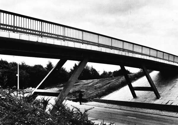
Westbury Place
Leeds. Over the M1
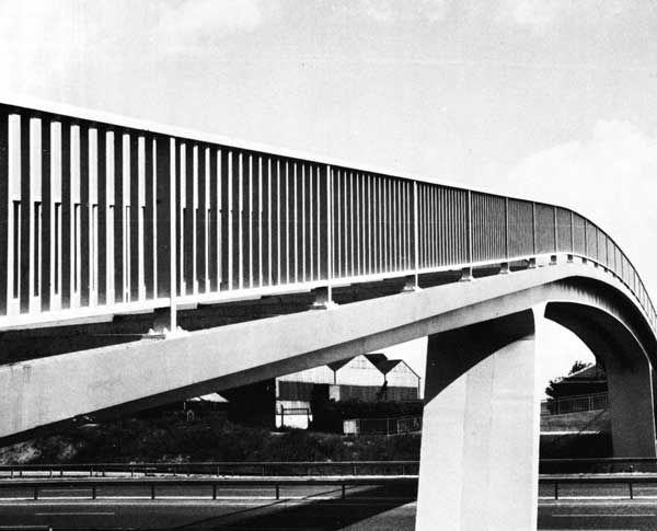
The footbridge spans the central carriageway of the M1 extension and the lower level slip roads at both sides. Several schemes in both steel and concrete were tried. Headroom considerations gave a final shape of curved central span and sloping side spans. Steel was chosen because it was suited to the slender shape required and the erection and construction procedures would minimize interference with construction traffic beneath.
The curved central portion was kept a constant depth due to the structural requirements at the centre of the span and over the legs, whilst the side spans were varied in depth. Inclined tapered legs were adopted to shorten the centre span whilst maintaining adequate lateral clearance at ground level. The fully welded structure of twin box section minimizes torsional problems on the 10ft wide structure and also gives a neat and easily maintained form to the bridge.
Stepped ramps on the wings minimize the length and the RHS welded to the edge of the deck plate conceal the steps in the ramps and the stiffeners to the underside of the cantilevered deck plate; they also serve as a base to the parapet. Sliding bearings are incorporated at the abutments to allow for temperature movement with pinned bearings under the main portal legs.
Owners: Leeds CBC
Engineer: A. E. Naylor, M Eng, C Eng, City Engineer and Surveyor, Leeds Steelwork Contractors: Downings (Barnsley) Ltd
Sheffield
Over Eyre Street
Part of the Eyre Street improvement programme, this bridge consists of two welded box girders 2ft 1in wide x 6ft apart with a ¼in thick steel plate stepped deck stiffened by 2½ x 1 ½in RHS at 4ft 6in centres. The structure was made in five sections each of 7 tons and delivered to site complete including hand railing. A DOE paint system was used and Dunlop Gripdeck compound was applied to the deck before delivery. Traffic in Eyre Street was stopped only for a short period early one Sunday morning when the centre span was positioned.
Owner: City of Sheffield
Engineer: A. Threapleton, C Eng MICE, Ml Mun E, City Engineer and Surveyor
Steelwork Contractor: Harry Peers & Co. Ltd
Glascote
Near Tamworth
The bridge is 16ft wide and has both cycle track and pedestrian walkway. Constructed of RHS, the bridge is 120ft long overall with a clear span of 70ft at road level. The central portal frames made from 18 x 10 x ½in Grade 43C RHS were site welded, and the side beams are 18 x 14 x ½in Grade 50C RHS. It is surmounted by three lines of RHS handraillng which has 2 x 2in posts, 5 x 2in horizontals and 1 x 1 in infill.
Client: Borough of Tamworth
Designed by: J. A. Maudsley, CBE, ARIBA, Dip TP, AMTPI, Architect to the City of Birmingham in association with A. Shaw, Ml Mun E, the Borough Engineer and Surveyor Tamworth
Consulting Engineers: Leonard Laing & Partners, Birmingham, R. A. Lycett (Construction Engineers) Limited, Tamworth