50 & 20 Years Ago
Erskine Bridge
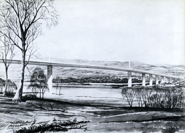
Artist’s impression of the completed bridge
There has been a ferry across the River Clyde between Erskine and Old Kilpatrick for centuries but the density of traffic has increased so much that one is now faced either with a long queue at the ferry or with a journey into Glasgow to use an alternative crossing. A new scheme has been drawn up linking the A8 (Glasgow-Gourock) and A82 (Glasgow-Inverness) trunk roads, costing over £8M. Erskine Bridge is part of this scheme.
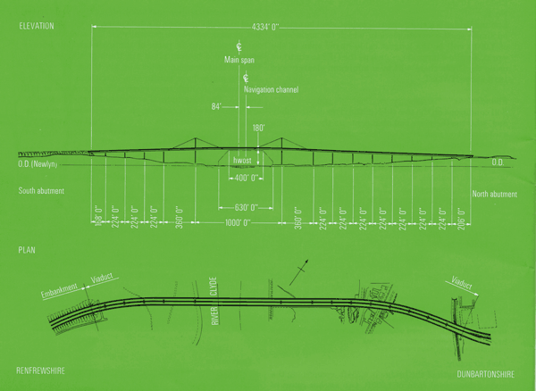
The bridge is a multi-span all-welded steel box girder on single shaft concrete piers in which the main span of 1,000ft will be the longest cable-stayed span in the world. To allow large ships such as the QE2 to continue using the Clyde there will be a minimum clearance of 180ft above HWOST.
Piers
The fourteen piers are all single diamond shaped shafts of heights varying from 22 to 175ft. The shape was developed to give a slender, graceful appearance and to offer minimum wind resistance. The piers are constructed of concrete and are designed to flex longitudinally to accommodate movements of the bridge due to temperature changes.
 Deck Structure
The total length of the bridge is 4,334ft, comprising the main cable-stayed span of 1,000ft, two anchor spans of 360ft, and twelve approach spans, four on the south side and eight on the north, generally of 224ft. The total weight of steelwork involved is about 11,000 tons. All movement due to temperature changes is accommodated by the rolling leaf expansion joint in the deck between piers 7 and 8, and by a toothed deck joint and roller bearings at both abutments.
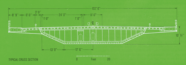 The steel deck girder is of elegant aerodynamic shape similar to those of the Severn and Wye bridges. It is generally 10ft 7½in deep at the centre with cantilevers on both sides to carry cycle tracks and footways. The total width varies from 102ft 6in at the main span, where the central reservation is wider, to 97ft 6in over the approach spans.
The supporting cables are 2½in diameter wire strands arranged in groups anchored to the steelwork in the central reservation and passing over 125ft high tapering steel masts of box section rising from the main piers.
The roadway surface is of mastic asphalt affixed directly to the steel deck plate. Design of the cycle tracks is such that they may be used to extend the carriageway whenever the expected increase in volume of traffic should warrant a third lane. Four 24in diameter water mains and two 12in diameter gas mains will be carried below the footways so that any maintenance on them will not interrupt traffic flow.
Fabrication
The all-welded trapezoidal box girder of high yield stress steel to B.S.968 consists of a deck plate, ½in thick throughout, sloping web plates generally 3/8 in thick but increased to 7/16 in thick and ½in in parts of the main and anchorage spans, and a bottom plate ½in thick at the piers, ¾in thick at the towers or otherwise 3/8 in thick.
All the plates have continuous longitudinal stiffeners which pass through transverse stiffening plates at 14ft centres. The longitudinal stiffeners for the deck plate are V-shaped at 2ft centres; those for the bottom flange and lower web sections are 8in bulb flats at 1ft 4in centres; for the upper and central web sections, they are 5in bulb flats at 2ft centres.
Diaphragms of stiffened plate, ¼in thick except over the piers where the thickness is increased to 1in, also occur at 14ft centres and they are welded to the transverse stiffening plates referred to above.
The steelwork is prepared and welded up in the fabricator’s shops into components suitable for transport to the site by road. These units are generally 56ft long, 8ft wide and 12 to 15ft deep. On arrival at the site they are offloaded either on the north or the south bank where site assembly yards have been established adjacent to the abutments. At the site the components are welded and bolted together to form 56ft long boxes complete with cantilevers ready for lifting into the bridge. The greatest care is taken in this assembly, by fabricating each box against its preceding and succeeding neighbours, to ensure that the boxes, which weigh from 120 to 160 tons each, will fit without difficulty when offered up at the bridge head.
Fabrication of the V-Shaped stiffeners is worthy of special mention. So far in Britain it had been possible to produce such members only by pressing and in lengths limited by the size of the press. Because of the advantages of continuous longitudinal stiffeners, however, the steelwork fabricator has developed a rolling process by which they can now be produced in any desirable length. This process involved the adaptation of machinery previously used for producing similar profiles but in lighter gauge material and of smaller girth. The V-stiffeners for Erskine Bridge are of ¼in thick high yield stress steel with a depth of 9in and a girth of 24in.
Erection
Erection of the steelwork is so planned that the centre will be reached from both ends simultaneously. This meant starting on the north abutment where the first two spans were erected by specially designed gantry cranes on falsework and welded up so that the remainder of the boxes could be erected by the cantilevering process.
Each succeeding box is lifted onto trolleys on the second span and winched out to the bridge head where specially designed launching girders are used to lower it and then to support it in position while it is welded to the preceding section.
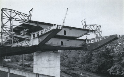
A view of the launching girder
The launching girders, developed from those used for the Wye Bridge, are then moved forward ready to receive the next box.
Before the last section of any approach span can be positioned, the cantilevered part has to be jacked up with the aid of a temporary prop to counteract the sag of about 4ft so that the next section will pass over the top of the supporting pier.
When the anchor and main spans are erected, special steps will be taken because the box is not strong enough to span the distances concerned. In the 360ft long anchor span, a temporary intermediate pier will be erected to limit the effective span to about 240ft. In the case of the main span, however, where the deck girder has to cantilever out 500ft to the centre, use will be made of permanent cables. When the girder cantilevers about 190ft, the steel mast will be erected over the main pier and some of the cable strands will be attached in temporary positions to support the steelwork while erection proceeds. As soon as the bridge head has advanced sufficiently (about 375ft from the main pier), the remainder of the strands will be attached in their final positions and the rest of the box sections can be cantilevered out.
On closing the bridge, the temporary cable strands will be fixed in their permanent positions.