Projects and Features
Entrance arrives at station
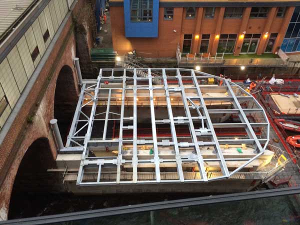
Cut-out of the completed entrance
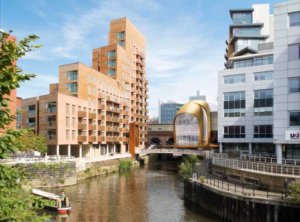
A portal-framed entrance structure, built over the River Aire, will help alleviate passenger congestion at Leeds station. Martin Cooper reports.
FACT FILE
Leeds Railway Station, new southern entrance
Main client: Network Rail, West Yorkshire Combined Authority
Architect: AHR
Principal contractor: Carillion Rail
Structural engineer: Mott MacDonald
Steelwork contractor: William Hare
Steel tonnage: 370tLeeds city centre is changing fast with numerous new and modern office developments helping it take on a dynamic post-industrial look.
Many of these new office schemes have been built in an area to the south of Leeds station and, in turn, they have created a demand for the new pedestrian station entrance currently under construction.
The existing main entrance is situated on the north side of the station and so commuters walking from the southern commercial schemes regularly cause pedestrian congestion on the pathways leading around the station. It has been estimated that up to 20% of the city’s rail passengers will benefit from and use the new entrance.
Available space for a new entrance to the south of the station was extremely limited and, as the design had to incorporate access to the existing high-level concourse, a location that straddles the River Aire was the only option.
Steel arrives by barge for the construction of the entrance frame
It may be the right choice of location but the new entrance’s site has presented the project team with a host of challenges.
“We’re building over water and so we have river safety issues, and apartment blocks on two sides mean the site is very constrained. The site also requires a large 63m-high tower crane which has been subject to numerous wind stoppages,” explains Network Rail Project Manager Luan Anderson.
“We are also working next to, and at times over, live rail lines so some of our work can only be done during night-time possessions.”
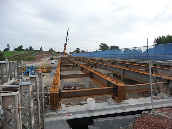
Prior to the erection of the steel-framed entrance superstructure, principal contractor Carillion Rail had to first install piled foundations and two concrete piers in the middle of the river (see box).
The piers are positioned and aligned with the existing rail viaduct arches so as not to impede the flow of the river during heavy rain. This has resulted in the requirement for a steel transfer structure at river deck level to support the primary superstructure columns of the new entrance, as they do not align with the piers.
The transfer deck represented William Hare’s initial phase of the steel erection programme. The steel was installed via the on site tower crane lifting the members off barges and positioning them directly between the new piers.
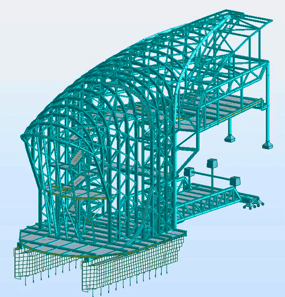
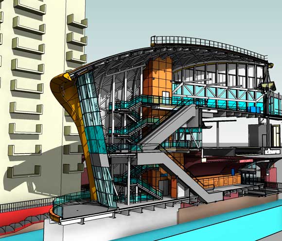
Model showing the entrance structure and the bridges spanning the rail lines and connecting into existing structures
The transfer deck comprises a series of galvanized beams, positioned at 1.8m centres. The beams span 10.2m between the new concrete piers and cantilever a further 3.5m beyond the centre line of each pier providing support to the columns above, as well as support to an access and maintenance deck around the perimeter of the building base.
The beams bear directly onto each pier via a simple baseplate connection. A series of beams cantilevers 2.3m beyond the southernmost primary beam to complete the curved plan profile of the deck.
“The main reasons why a steel deck was specified were the benefits brought by offsite fabrication and speed of erection to reduce the construction time above the river, which was considered to be a positive health and safety decision,” says Mott MacDonald Project Manager Jon Svikis.
Holorib metal decking fabricated and cut to size offsite spans between the beams and provides permanent formwork from which to safely fix reinforcement and pour a 160mm deep concrete floor slab. Pockets were left in the slab ready to receive the superstructure columns and vertical bracing.
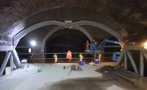
Existing arches have been strengthened with steelwork

Steel waiting to be loaded onto barges at the Water Lane yard
Extending from the transfer deck is a new suspended floor and escalator pit that extends through the existing masonry arch. The floor structure comprises two upstand trusses that span 15m and are 2.1m deep.
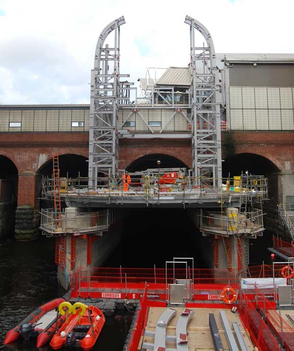
Sitting on the transfer deck, the entrance superstructure comprises a series of portalised arches at 1.8m centres.
“The close spacing is to allow the structural zone to be minimised, reduce the load on each transfer beam at river deck level, and to allow the sweeping, curved roof geometry to be achieved without the need for a secondary frame, thereby minimising the overall cladding build-up and maximising the internal space available,” says Mr Svikis.
The portals are a maximum of 20m tall, with a horizontal span of approximately 12.5m. Each frame comprises two vertical legs and a curved arch section of varying radii of between 2.8m and 12.3m.
Generally the frames are being erected in four pieces. The frames are braced out of plane via a series of SHS members, forming an inherently stable ‘diagrid type’ structure. In-plane stability is provided via moment action of the individual frames, as well as via the 20m-high braced lift shafts that are positioned to the north adjacent to the existing masonry viaduct. There are 11 frames at river deck level; with a further nine frames extending above three existing railway lines to form the connection with the high level concourse.
This involves construction of a new ‘Ticket Barrier level’ above platforms 15,16 and 17, crossing three electrified railway lines. The new ticket barrier level concourse is hung from two primary trusses that span across the lines and were installed during weekend rail possessions. The eastern truss spans 17.7m and is 1.9m deep, while the western truss spans 19.5m and is 2.3m deep.
To help support the concourse extension a new column has been introduced on platform 15 on top of the existing Victorian masonry viaduct.
This has meant one of the viaduct’s arches had to be strengthened with four plate girder ribs arranged in a cruciform. The steelwork is packed tightly to the existing masonry arch using high strength cementicious grout. The steel sections are 365mm deep and 325mm wide, fabricated from 45mm plate for the flanges and 25mm plate for the webs. Each of the four ribs is bolted into the existing masonry pier at the springing point via 1m deep haunches and 40mm thick end plates.
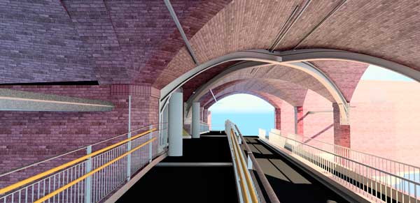
As well as the access points from the high level concourse, low level access to the new entrance will be provided by two footbridges (see box) spanning from both banks of the river and ramps leading into Dark Neville Street within the viaduct arches.
Leeds station southern entrance is due to be completed this autumn.
 River work
The location of the site means much of the work revolves around the River Aire. Carillion Rail has its main compound and an assembly yard about 1km downstream at Water Lane. Much of the project’s materials arrive at this yard and are then delivered to the project by barge as this is the easiest way to access the site without negotiating the surrounding narrow streets.
“One of our initial tasks was to assemble a jack-up barge and float it to the site,” explains Carillion Project Manager David Carlyle. “At 18m wide the barge provided a working platform for our 26t piling rig and an area from which we constructed the two concrete piers.”
Steelwork contractor William Hare is also delivering all of its steel to the site via Water Lane, using a number of pontoons that can be configured to suit the length and weight of the steel members.
Footbridges
 There are two external footbridges that will provide access for passengers from the east and west riverbanks into the new entrance, as well as two further bridges/ramps leading into the viaduct arches.
The eastern footbridge spans 9.5m, while the western bridge spans 12.8m. Both bridges are welded structures comprising two primary box sections supporting an arrangement of stiffened deck plates and secondary sections.
The eastern bridge will be brought to site as one fully completed element and craned into position, while the western bridge will be brought to site in two pieces. This is due to the crane lifting capacity restrictions. The shorter section will be temporarily propped before the larger section is craned into position. The two elements will then be spliced together insitu above the river.
 Steelwork for the new south entrance to Leeds station
Dr Richard Henderson of the SCI
The structure of the new south entrance consists of curved 400 mm × 200 mm RHS rafters on RHS columns of the same size, forming a series of portal frames. In elevation, looking from the south, the curved beams have a number of different radii to form the required roof profile and are closely spaced, matching the spacing of the transfer deck beams which support them. The portal frames are designed elastically with pinned feet for strength, but some fixity is assumed to control the lateral deflection when considering serviceability.
The columns are closely spaced to eliminate the need for secondary structure spanning from frame to frame to support the cladding: the cladding itself is sufficiently strong and stiff to span the 1.8m between frames. Perpendicular to the plane of the portal frame, the frames are connected together with bracing which forms a diagrid over the whole of the vertical sides and the curved roof. The structure is very stiff out of plane and the diagrid ensures load-sharing between the transfer deck beams. Lateral loads are also shared between the diagrid and lift shafts next to the existing masonry arches of the existing railway platform structure. It was a design requirement that the new structure is structurally stable independently of the existing structure.
The portal frames were divided into four pieces for manufacture and transportation, consisting of the two straight legs and two curved pieces forming the rafter. The splice in the rafter occurs at the highest part of the curve. All splices carry axial and shear forces and bending moments as in traditional portal frames.
The cladding wraps tightly round the structure as already described. To prevent the connections in the portal frames from intruding into the cladding zone, conventional “pipe flange” type splices with end plates projecting beyond the envelope of the RHS were avoided. Instead, transition pieces formed of shallower open sections were welded to end-plates closing off the RHS elements. End-plate splices to these transition pieces were then detailed within the RHS profile, avoiding the encroachment into the cladding zone. The curved rafters were bolted together in the assembly yard, brought to site by barge and lifted onto the columns as a single element. The curved beam-to-column connections were made in position.