Projects and Features
Complex roof tops school
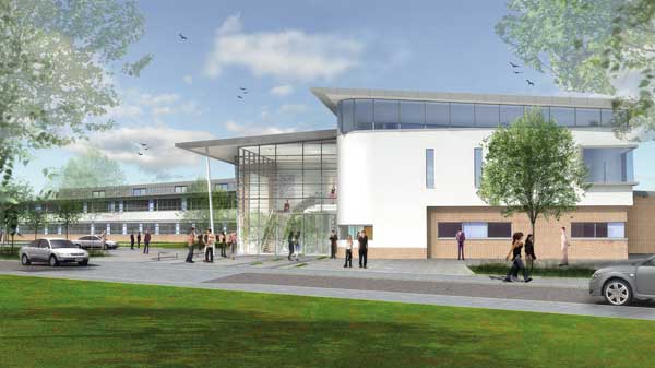
The new school will boost Antrim’s economy
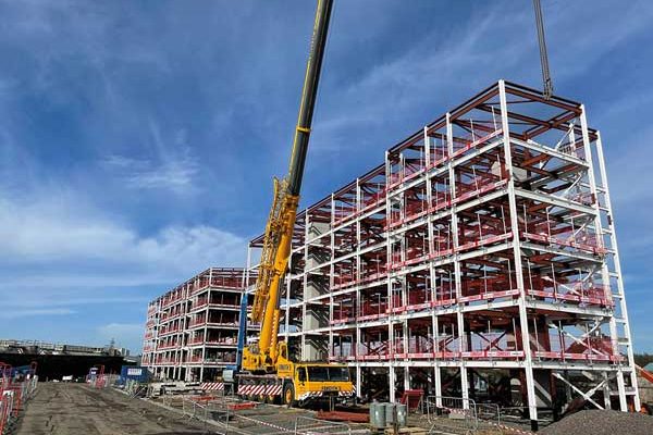
Steel construction has taken a leading role in the design and building of a new school in Antrim, Northern Ireland.
Parkhall Integrated College, Antrim
Main client: Education Authority
Architect: BDP
Main contractor: O’Hare & McGovern
Structural engineer: BDP
Steelwork contractor: Walter Watson
Steel tonnage: 650tA £20M new school project, funded through the Northern Ireland Department of Education’s capital build programme, is taking shape in the town of Antrim.
Known as Parkhall Integrated College, it will replace the nearby existing school, which will be demolished as part of the final element of the project providing space for new sports pitches.
Construction work began last year on the greenfield site that previously accommodated the school’s playing fields. Main contractor O’Hare & McGovern undertook some groundworks prior to installing pad foundations in readiness for the steel frame to be erected.
Approximately 650t of structural steelwork is being fabricated, supplied and erected for the project by Walter
Watson.
“The building on plan is a skewed H-shape, and the main challenge for us has been maintaining the ridge heights as well as marrying in the roof slopes at the various intersections,” says Walter Watson General Manager Structural Division Trevor Irvine.
“As the school is a mix of single and two-storey parts the roof structure has some very complicated interfaces and geometry where sloping and curving elements meet,” adds BDP Project Engineer David Nicholls.
The lower parts of the two vertical legs of the H-shape are two-storey, as is the spine that links the two legs together. These areas accommodate classrooms. Elsewhere the school structure is single-storey, interspersed with double-height areas.
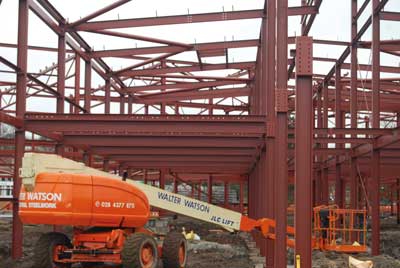
Steelwork contractor Walter Watson used its own fleet of cranes and MEWPs
Each of the legs are different lengths with the northern one measuring 125m-long by 40m-wide, and the southern leg measuring 77m-long by 40m-wide, while the interconnecting spine is 80m-long by 20m-wide.
The longer of the legs accommodates a sports hall and associated changing rooms, a gym, kitchen and dining hall, and breakout areas.
“Steel was chosen as the framing solution because it is quick to erect and for its long span qualities,” says Mr Nicholls.
The sports hall has a span of 16.5m and the dining hall has a 15m span. These would have been difficult to achieve using a different framing material.
Approximately half of the opposite leg houses a single-storey technology block featuring a triple mono-pitched roof with windows on the vertical sections.
Structurally the school is a braced frame with tubular cross bracing positioned in partitions and walls providing the stability. Because the H-shaped building is so big it had to be divided up and so there are two movement joints, one at the end of the central spine block and a second splitting the longer northern leg in half.
Summing up the project, Northern Ireland Education Minister John O’Dowd says: “This significant investment will allow the college to move from its current split site arrangement to a brand new purpose-built school.
“This not only benefits the school and its pupils, but it will also be a boost to the local community and businesses.”
Catering for pupils aged between eight and 12 years old, the school is being constructed for 735 students and it will open its doors from September 2017. The entire project, including the demolition of the existing buildings and the creation of new sports pitches will be completed by 2018.
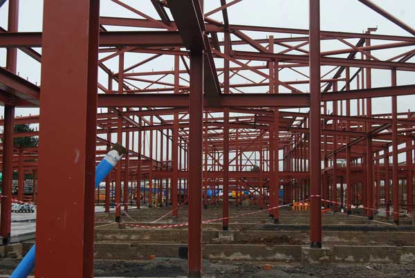 Steel erection
Steel construction was carried out with Walter Watson using its own fleet of mobile cranes and MEWPs. The cranes used were 60t-capacity units and MEWPs had reaches of 45 ft to 65 ft.
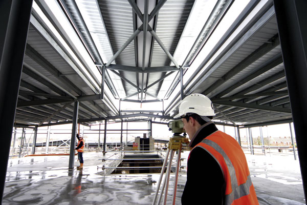
All of the steelwork was erected up to and including roof level. The cold rolled purlins were omitted to allow erection of the first floor precast slabs.
After erection and grouting of the slabs, the purlins were then subsequently installed using a crane sitting outside the footprint of the building, and two compact scissor lifts operating from the first floor precast slabs.
Parkhall College Movement Joints
Dr Richard Henderson of the SCI discusses the movement joints in the building footprint.
Where movement joints are introduced into a building, the resulting portions are often treated individually, each having its own vertical structure and lateral stability systems. Where the constraints of the architecture prevent this, certain forces have to be transferred across the movement joint whilst still allowing the necessary movement to take place. This requirement provides challenges to the designer which are not otherwise encountered.
 The need for, and pros and cons of, movement joints are discussed in Steelwork Design Guide to BS 5950, Part 4 Essential Data for Designers, 1991 (SCI publication 070). The practical issues associated with joints are discussed in Chapter 7 which remains the best guidance available at present. Thermal movements of 24mm per 100m length of building are calculated for a 20 degree temperature change assuming free expansion, and maximum thermal stresses of about 50MPa for the same temperature change assuming the thermal strain is fully restrained.
Parkhall College’s building footprint is roughly H shaped. Two legs of different lengths (one 125m long) are joined by a cross bar. The legs of the H are not parallel. Movement joints have been introduced into the footprint at one end of the cross bar and across the 125m long leg.
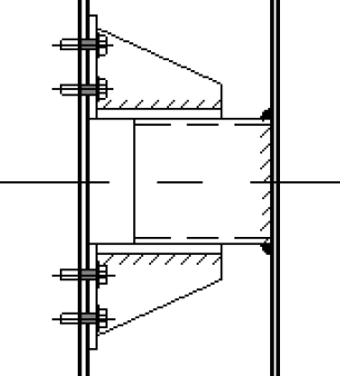
At the joint introduced part-way down the 125m leg of the building, beams parallel to the direction of thermal movement cross the joint and are supported by beams or columns on the other side. The movement is accommodated in the connection by a sliding bearing with bolts in slotted holes providing a guide. Where the floor slab is continuous on each side of the joint a beam is provided on each side of the joint.
The floors on both sides of the movement joint are required to move together. This is achieved by providing a series of shear keys at regular intervals along the joint. SHS stubs are welded to the beam web on one side of the joint. Pairs of stiffened angles are bolted to the beam web on the other side of the joint, with the legs spaced so as to allow the SHS stubs to fit between them (see the figure). The arrangement allows relative vertical movement and horizontal movement perpendicular to the span of the beams but transfers horizontal shear force across the movement joint from the diaphragm on one side into that on the other.