Technical
Cladding Interfaces with Structure
Dr Richard Henderson of the SCI highlights the effects of structural frame movements on curtain walling and shows why standard live load deflection limits are too relaxed for edge beams.
Introduction
The principal function of cladding on a building is to separate the external and internal environments. It is also used by the architect and the building owner to create a visual statement. The accuracy of manufacture and installation of cladding panels is clearly seen at the joints which must be to true line and level. Building movements also become obvious at the joints and must be controlled.
There are different generic types of cladding and many different materials used. Office buildings commonly feature curtain walling, so-called because the original concept involved elements suspended from the top of a building elevation like a curtain. Cladding often involves brittle materials (glass, stone), onerous manufacturing and installation tolerances and is of high value. The building envelope cost can be two or three times that of the frame.
Curtain Walling Systems
There are two generic types of curtain wall systems commonly in use: “stick” and “unitised”. Stick systems are built up on site from components to make up the curtain wall: vertical mullions and horizontal transoms are used to form a rectangular grid. Glazed vision panels formed of double or triple glazed units and solid insulated panels fill in the grid to form the remainder of the curtain wall. Solid panels concealing the floor structure and ceiling void are referred to as spandrel panels.
Stick curtain wall is frequently used on low-rise buildings (eg two to five storeys) in limited quantities, where the area required does not justify the investment in a bespoke design. The mullions may extend over two or three storeys. Several stick curtain wall systems are commercially available.
Unitised curtain walling consists of factory-made, interlocking storey-height panels which are delivered to site and installed progressively. The manufacturing tolerances are to 1 or 2 mm. The components may be designed for a specific building and may involve the design of new structural shapes for the mullions and transoms to provide the desired architectural features. Mullions and transoms are made from aluminium extrusions because complicated shapes can be easily and accurately formed. The extrusions on the vertical edges of the panel interlock to form a split mullion at the panel joint. Interlocking transoms form the horizontal edges. Weathertightness depends on accurate interlocking of the elements and proper functioning of gaskets in the joints.
Interfaces with the Structural Frame
Curtain walling is usually suspended so the weight of the wall is applied to the building frame at the top of the mullion. In a stick system, this may not be at every floor level. A unitised system will usually apply gravity loads to the frame at each level. The geometry of both stick and unitised systems is usually based on a 300mm planning grid. Unitised panels may be 1.2 or 1.5m wide or multiples of these with sizes and weights determined by transportability and ease of handling.
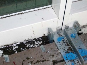
Gravity brackets are usually fixed to the top of the slab at the floor edge and hidden beneath a raised-access floor. Curtain walling manufacturers usually have their own bracket system which involves adjustability in three orthogonal directions. Adjustments perpendicular to the plane of the curtain wall and horizontal in-plane adjustments are achieved by cast-in channels and serrated brackets with slotted holes and serrated washers. The length of slots provides sufficient adjustment to achieve a true line. Gravity loads are transferred through vertical bolts with screw-adjustments to achieve vertical alignment. Restraint against out of plane loads is provided at gravity brackets by T-shaped slots or similar positive engagement (Figure 1). At the bottom of the mullion, a spigot fixed into a cavity in the extrusion engages with the extrusion below, thus providing a means of transferring shear force while allowing axial movement.
The weight per linear metre of curtain walling depends on the floor to floor height of the building and on the materials of construction and features included in the design. The weight of a 4.0m x 1.5m unitised curtain wall panel with full-height glazing and a stone-faced spandrel panel could be 4.0 kN or more. Metal-faced insulated panels and double glazing from desk-height to ceiling could weigh as little as 2.0 kN.
Stick curtain walling mullions are supported at the top by gravity brackets in the same way as unitised panels. If mullions extend past more than one floor, the brackets at the intermediate floor levels provide restraint to horizontal loads but allow vertical movements to occur.
Installation
Curtain wall installation takes place after concrete floors have been poured so that cast-in channels are in place. Unitised curtain walling panels are lifted onto projecting landing platforms and stored on the floors. Gravity brackets are fixed to line and approximate level. Installation tolerances to line and plumb are within about 2 mm. The first panel is installed and levelled using the adjusting screws in the bracket fixing. Subsequent panels are erected so that the split-mullions engage with each other, and adjusted for level, progressively round the building. The closing panel is slid vertically down between the panels already erected on either side.
Accommodation of movement after installation
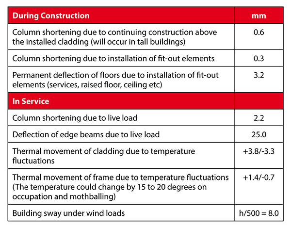
After installation, the cladding has to be capable of accepting building movements and continuing to perform. Movements result from column shortening, beam deflection due to superimposed dead and live loads, thermal effects and the effects of sway due to wind loads. Estimated values of movements are given in the table. Columns are assumed to be of grade S355 steel with a 4.0m storey height on a 9m grid. Beam deflection figures are based on live load deflection limited to span/360.
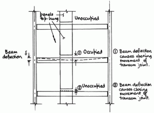
Both the interlocking transoms and the mullion joints are required to accommodate the in-service movements of the frame and maintain weathertightness. Where occupied floors are next to unoccupied floors, both opening and closing movements will occur (Figure 2). Excessive closing movements will result in the transfer of load through cladding elements not designed to sustain it; excessive opening movements could result in the weathertightness of transoms being compromised. Excessive sway could result in the edges of a glazed unit coming into contact with the mullion. Allowances in the curtain wall designed to deal with in-service movement must not be consumed by the accommodation of frame elements which are out of agreed tolerance.
Approximate magnitude of in-service movements
An example is given below for a change in tenancy involving new tenant fit-out on one floor of a building using the values tabulated above. Closing movements have been shown as positive; opening movements have been shown as negative. Beam deflections based on span/1000 have also been tabulated.
These movements occur on emptying and stripping-out the floor and are reversed on refitting and reoccupation. Closing movements due to column shortening of 2.5 mm will already have occurred. The cases shown occur if the maximum thermal movements coincide with the change in occupancy.
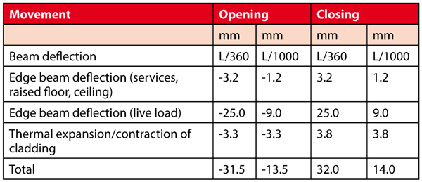 The maximum closing movement relative to installation is 32.0 + 2.5 = 34.5 mm for 9m span beams with a deflection limit of span/360. As expected, the edge beam deflection is the dominant component, contributing up to about 82% of the movement for this case.
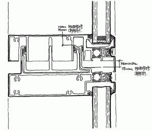
The maximum deflection that can be accommodated in typical unitised curtain walling panels installed to correct tolerances and clearances is about 15 mm (Figure 3) and in stick curtain walling systems it is even lower – about 8 mm. It is clear that a deflection limit of span/360 is inappropriate for edge beams supporting cladding. Lower deflections must be achieved eg as given by span/1000 for unitised curtain walling for a 9m span beam. SCI document P183 Design of Semi Continuous Braced Frames shows that in practice, nominally simply supported beams in conventional construction can achieve a degree of end-fixity which will be sufficient to reduce the edge beam deflection significantly. This fact is no-doubt the reason that there have been few reported occasions when excessive deflections of the supporting structure have caused problems with curtain walls.
Conclusions
- Cladding movements are dominated by the edge-beam deflection under live loads.
- Significant movements can occur during the life of the building due to changes in occupancy.
- The capacity of curtain walling to accommodate movements is about 15mm for unitised systems and 8mm for stick systems.
- Excessive movements could either result in damage to a high-value building system due to inappropriate load transfer or leaks which are immediately obvious to the building occupants.
- Deflections under live load of edge beams supporting curtain walling should be discussed early in the design process and special limits agreed. Absolute limits of about 8mm may be appropriate for unitised curtain wall systems. Economy can be achieved by taking advantage of connection stiffness to reduce the predicted beam deflection.


