Technical
Building Consequence Classes and the link to Execution Classes
Richard Henderson of the SCI discusses the evolution of Building Consequence Classes and the link between them and Execution Classes of structures.
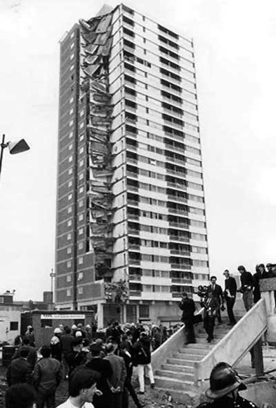
Figure1: Ronan Point Flats
The Building Regulations
Building Consequence Classes have their origin in Approved Document A to the Building Regulations and the provisions for disproportionate collapse in section A3. The need for such provisions was exposed by the partial collapse of the 23-storey Ronan Point flats in 1968 following an accidental gas explosion in a kitchen on the 18th floor. (see Figure 1).
Section A3 of Approved Document A (AD-A) gives the requirement in the Building Regulations itself and its limitations and guidance as to how the requirements may be met. In the 1985 Building Regulations, requirement A3 stated “The building shall be so constructed that in the event of an accident, the structure will not be damaged to an extent disproportionate to the cause of the damage”. The requirement was applicable only to: (a) a building having five or more storeys (each basement level being counted as one storey); and (b) a public building, the structure of which incorporates a span exceeding nine metres between supports. The guidance in AD-A advised the Building Regulations could be met for steel buildings by designing to BS 5950: Part 1: 1985 where recommendations for the provision of horizontal ties for all buildings were made. Additional recommendations were made for “tall” buildings for vertical ties and, where necessary, localization of damage. The latter recommendation resulted in the provision of key elements where notional removal of an element resulted in damage over an unacceptably large area.
The 1991 Building Regulations amended the wording but not the sense of the requirement. The limits on application removed the reference to a public building including a span of over nine metres. Guidance given in BS 5950 was that horizontal and vertical ties were to be provided but where effective vertical ties were not feasible, a check on the potential area of collapse was to be made by considering notional removal of the element and limited to a maximum of 70 m² or 15% of the floor area, whichever is the smaller. If this check failed, the element was to be designed as a “protected member” or key element.
The Building Regulations 2000 included the same requirement A3 as the 1991 Regulations: “The building shall be constructed so that in the event of an accident, the building will not suffer collapse to an extent disproportionate to the cause”. No limits on application were made. Instead, guidance depending on the class of the building was provided in AD-A on appropriate approaches to ensure sufficient robustness of a building to limit the extent of damage or failure without collapse. The building classes were presented in Table 11 in AD-A. The primary function of the building classification was to establish what structural arrangements were to be made by the structural engineer for a particular building to ensure satisfactory robustness.
The Building Regulations 2010 (the current edition) includes exactly the same requirement. In the guidance in AD-A, building classes are renamed building Consequence Classes (CC) and are shown in Figure 2 (Table 11 from AD-A) on p26. The guidance in AD-A states the requirement will be met if horizontal ties are provided for CC2a; vertical ties are added for CC2b and a systematic risk assessment is carried out for CC3 buildings. The alternative notional removal of columns and provision of a key element where the area at risk of collapse is too extensive is also included. The maximum area is increased from 70 m² to 100 m².
The number of storeys and floor area are the principal determinants of the building Consequence Class. The potential number of people harmed in the event of a collapse is also an important factor.
Figure 2: Approved document A Table 11
The National Structural Steelwork Specification and EN 1090-2
In 1989, the first edition of the National Structural Steelwork Specification for Building Construction (NSSS) was published for the execution of steelwork by people with full knowledge and understanding of BS 5950. It coincided with the introduction of the British Constructional Steelwork Quality Assurance Certification Scheme (now SCCS), based on the requirements of BS 5750 Parts 1 and 2, precursor to ISO 9001. The NSSS was conceived to achieve greater uniformity in contract specifications issued with tender and contract documents. The first edition covered outline requirements for the design, materials, preparation of drawings, fabrication, erection and protective treatment of structural steelwork which is to be used for all types of building construction. The (current) Fifth Edition CE Marking Version was published in October 2010.
The clauses of the latest version fully complies with BS EN 1090-2: Technical requirements for steel structures, introduced in 2008. This standard introduces the concept of Execution Class (EXC), a significant addition to the original requirements of the NSSS. It is a classified set of requirements specified for the execution of the works as a whole, of an individual component or part thereof. The stated reason to differentiate between the classes is to provide a level of reliability against failure or malfunction of the structure that is matched to the consequences of failure.
Execution Classes
The default Execution Class to which BS EN 1090-2 is applicable is EXC2 (cl. 4.1.2). The NSSS scope states the specification is based on the execution of structures in EXC2 and it is not intended for structures which are subject to fatigue or seismic loading. The requirements of the NSSS are in general more onerous than those of EXC2 in BS EN 1090-2. Additional requirements of EXC3 over EXC2 are principally aimed at reducing defects in the material, producing a higher quality of welding and increasing the level of inspection of the work. The National Foreword to BS EN 1090-2 suggests that as a default basis, EXC2 could be specified for structures/components/details used in buildings, and EXC3 could be specified for structures/components/details used in bridges where fatigue needs to be considered in design. The additional requirements in EXC3 may therefore be considered to be at least part of those necessary for structures subject to fatigue.
BS EN 1993-1-1:2005+A1:2014 was issued in June 2015. Amendment 1 involved the inclusion of Annex C which places the basis for the selection of Execution Class in the design standard. The UK National Annex issued at the same time sets out the UK approach to selecting the Execution Class. Structures in Consequence Classes one and two are to be minimum EXC2. Structures in Consequence Class three are to be EXC3. The NSSS is therefore applicable un-amended to structures in CC1 and CC2 but structures in CC3 require additions to the NSSS, as outlined in BS EN 1090-2.
Effect of the Consequence Class as a differentiator
The use of the Consequence Class to differentiate between Execution Classes is a blunt instrument. As in all circumstances where there is a step change in requirements on either side of a boundary between regions of a continuum, instances which just fall on the more onerous side of the boundary may be considered to be unreasonably penalized. This issue is illustrated in the following two figures which show hypothetical building arrangements. Both buildings are of conventional simple construction with a regular grid, with braced frames providing stability. Neither building is subject to fatigue.
Figure 3: 15 Storey office building
Figure 3 is a stick diagram of the structure of a 15-storey office building with 9 m by 9 m bays. The floors are 8 bays by 7 bays giving a floor area of 4,536 m² and a total area over 15 floors of about 68,000 m². At an occupancy rate of one person per 10 m² of net floor area, the number of occupants could well exceed 5000 people. This structure does not exceed 15 storeys or 5000 m² per storey and therefore meets the requirements for Consequence Class 2b. The Execution Class for the structure is therefore EXC2.
Figure 4 is a stick diagram of the structure of a 2-storey shopping centre, also with 9 m by 9 m bays. The floor is 8 bays square giving a floor area of 5,184 m². The floor area exceeds 5,000 m² and therefore falls outside the requirements for Consequence Class 2b and the structure is Consequence Class 3. The Execution Class for the structure is therefore EXC3.
Figure 4: Two storey shopping centre
The office building requires horizontal and vertical ties. The shopping centre requires a systematic risk assessment to determine the provisions for robustness. Such an assessment may well conclude that no special provisions for robustness are required and in practice, horizontal ties alone will be sufficient. As the columns are all likely to be continuous over the two storeys, no consideration of vertical tying is necessary. Nevertheless, the office building is in EXC2 and the shopping centre is in EXC3
In the case of the shopping centre with a regular grid and conventional structure, what benefit is there of requiring that the Execution Class is 3? Does either the employer or the user gain from greater reliability? Compared with the office building, the potential number of occupants is likely to be less so fewer people are likely to be affected by any loss of a column
Approved Document A does offer an alternative approach to using Table 11 to determine the Consequence Class of a building, set out in documents referred to. These documents give the background to the building classes in Table 11. The approach is specific to a building and may result in its allocation to a lower Consequence Class than Table 11.
Conclusion
Execution Classes can be applied to a whole structure, a part or specific detail. If a transfer structure was included in a CC2b building, it is likely to be designed as a key element and EXC3 can be specified for this part at the discretion of the structural engineer. It seems equally appropriate in the case of a regular, conventional structure which falls outside the requirements of CC2b, such as the shopping centre illustration above, that the structural engineer be given the ability to choose Execution Class 2. Perhaps a more appropriate approach would be to place building structures not subject to fatigue in EXC2 and require significant parts such as transfer structures to be in EXC3.