Projects and Features
Banking on steel
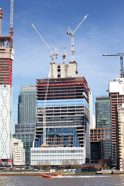
The latest steel-framed office tower at Canary Wharf features a sloping western façade as well as a flexible design based around cellular beams.
Fact File
One Bank Street, Canary Wharf, London
Main client: Canary Wharf Group
Architect: Kohn Pedersen Fox
Main contractor: Canary Wharf Contractors
Structural engineer: Arup
Steelwork contractor: William Hare
Steel tonnage: 9,500t
London’s Docklands has been a hive of construction activity since the early 1990s and one area in particular, Canary Wharf, always seems to be playing host to yet another high-profile high-rise project.
Within a stone’s throw of One Canada Square, a building that lays claim to being the UK’s second tallest structure and a project that kick-started the entire Canary Wharf development, another steel-framed office is under construction.
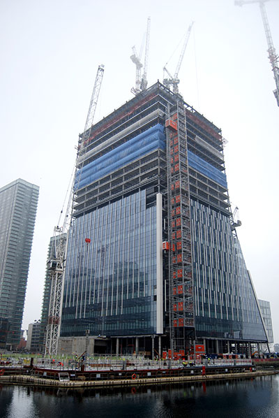
One Bank Street is a 27-storey commercial building that will offer 60,000m2 of high-quality office space including three levels of state-of-the-art trading floors, a retail unit at ground level, a free-standing retail kiosk on South Dock Promenade, public realm, planting and landscaping, and basement car and cycle parking.
Designed by world-renowned architects Kohn Pedersen Fox, One Bank Street will contribute to strengthening the role of Canary Wharf as a prime London office and employment location, providing capacity for an additional 5,837 full-time jobs.
Designed to achieve a BREEAM ‘Outstanding’ rating, the steel-framed structure sits atop a triple 16m-deep basement and gains its stability from a large centrally-positioned reinforced concrete core.
Attached to two sides of the concrete core, the building features another outer ‘soft core’ that accommodates risers.
“To maximise the flexibility of this space it was established at concept stage that the MEP zone would be framed in steel, with a line of columns located at the outer edge on each face, with shallow steel beams spanning to the core to suit the riser layout,” says Arup Associate Dominic Munro.
The steel columns adjacent to the core are part of a vertical steel truss system, which transfers all the vertical loads to the core. The diagonal members of the truss are, in effect, hangers supporting the floor below. The main advantage of this truss system is that the load in the steel columns is greatly reduced.
“We have estimated that approximately 600t of steel was saved as a result of this idea. The concrete core benefits from the additional vertical load as tensile stresses from wind loading are reduced. The continuous truss also means that there is very little differential movement between the steel and concrete elements of the core,” adds Mr Munro.
Adjacent to the core, the building has two large atrium spaces that are separated by a floor slab at level eight, which is supported from above by inclined hangers. The lower atrium extends upwards from level four to the separating slab, while above the second atrium then proceeds upwards to level 10.
The steel frame is primarily arranged around the core with Fabsec cellular beams radiating outwards on all four elevations to create column-free spans of up to 14m to the perimeters.
Many of these cellular beams have in-built flexibility, as they have additional holes for future services routing.
An exception to the column-free design is the sloping western elevation, which overlooks the River Thames.
From the top of level three to level 12, a series of raking columns facetted on each floor, create a feature slope which then continues upwards less steeply to level 23, via cantilevering floors, until level 23 where the elevation becomes vertical.
Along this elevation, the structure’s internal floorplate is no longer column-free, as at level four there are two lines of internal columns. However, as the slope decreases the size of the floorplate, there is only one line of columns by level eight and none are present by level 12.
According to Dominic Munro, each floor along the raking façade has to resist a horizontal compressive force which is a function of the given floor’s load (plus the effect of any additional change of inclination).
This results in the building leaning onto the core and pushing it towards the east.
“In order to mitigate this effect, we came up with the idea of breaking the two corner raking columns at levels where they come near a vertical column, namely level 14 and level four,” says Mr Munro.
“Where the breaks in the raking columns occur, loads are transferred to nearby vertical columns via transfer beams. This has the double advantage of reducing the force running down the raking columns, and hence the forces leaning on the core, and also creates a balanced system whereby the transfer floors and the stability core are subject to a symmetric set of forces with no overall twisting effect.”
Although the raking columns continue all the way down to ground level, they are absorbed into a more traditional rectangular three-storey element at the tower’s western lower levels.
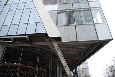
Three floors (first to third) cantilever out by 4m to avoid a line of perimeter columns that would obstruct a pedestrian thoroughfare.
This cantilever is formed by a series of 10m-long plate girders positioned at first floor, each weighing 44t. The installation of these members required steelwork contractor William Hare to use a 250t-capacity mobile crane.
“Most of the remainder of our 9,500t steel tonnage has been erected via tower cranes that are positioned on top of the core,” explains William Hare Senior Site Manager Ben Burns, “apart from the 90t perimeter columns which required a 90t-capacity mobile crane to be brought to site.”
One Bank Street is due to complete during 2019.
Soft cores
One Bank Street adopts the familiar approach to office building construction of concrete core surrounded by steel frame with some particular features. Richard Henderson of the SCI discusses some of the details.
 The construction sequence at One Bank Street required the concrete core arrangement to be fixed and under construction before the details of risers for building services were finalised.
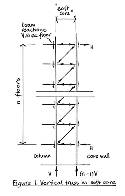
This led to the adoption of a “soft core” in a 4m zone on the long east and west sides of the concrete core which could be finalised later, bounded by a row of steel columns. Inclined hangers and horizontal beams in vertical trusses between the columns and the core wall transfer vertical load to the concrete core.
The horizontal component of the axial tension in the inclined hangers is balanced by the thrust in the horizontal beams, with connections to cast-in plates which transfer the vertical load into the core walls through reinforcement. The inclined hangers are arranged to carry the same loads where possible so that out of balance forces are minimised. Horizontal forces on the core are present at the top and bottom of the vertical truss where inclined hangers are not provided. The principles are illustrated in Figure 1.
Inclined columns
The west elevation of the building is sloping over much of its area with inclined columns in the external face. At the connections of beams to the inclined columns, the triangle of forces composed of the vertical reaction in the beams and the increase in the inclined column axial load is resolved by a horizontal force in the beam. The inclined columns are in effect leaning on the concrete core.
This force is transferred into the concrete floorplate and resisted by the core. The axial forces which are in the same load case as the vertical loads are thus not transferred to the core through the steel floor beams, avoiding the need to design the beam connections for coincident shear and axial forces. If the inclined columns are continued to the ground, the horizontal forces on the core are also carried to the foundations.
However, by breaking the inclined columns, the horizontal component of force at the break is transferred back to the core, balancing the axial forces above. The result is that there is no shear force on the core due to the adoption of inclined columns that is carried through to the foundations.


