Technical
AD 354: Resistance of bolted connections in tension, for design to BS EN 1993-1-8
This Advisory Desk Note provides a simple method of determining the design tension resistance of bolted connections in accordance with BS EN 1993-1-5:2005 that avoids the need to evaluate prying forces. The method is based on the simple method provided in BS 5950-1:2000.
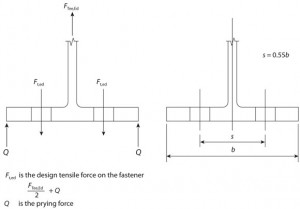
The design tension resistance (Ft,Rd) of individual fasteners is given by BS EN 1993-1-8, Table 3.4. However, in a tension connection, Clause 3.11 requires that the fasteners should be designed to resist a design tensile force (Ft,Ed) that includes any force due to prying action (see Figure 1 below). Clause 6.2.4 provides rules (in Table 6.2) for T-stub flanges that implicitly account for prying forces.
In contrast, BS 5950-1 has two approaches to verify the tension capacity of connections using bolts – the more exact method of clause 6.3.4.3, which corresponds to the Eurocode method and which also requires the consideration of the prying force, and the simple method of clause 6.3.4.2. The simple method of BS 5950-1 utilises a reduced “nominal tension capacity” (equal to 0.8 × the tension capacity) that is verified against a tensile force that excludes prying force; this means that, in certain circumstances, designers need not calculate the prying force.
This Advisory Desk recommends that, for verifying resistance of a bolted tension connection when designing to BS EN 1993-1-8, as an alternative to the ‘exact method’ of Table 6.2, the following simple approach may be adopted, provided that the cross-centres (gauge) of the bolt lines are not greater than 55% of the flange width or end plate width (see Figure 2):
Calculate the design forces in individual fasteners, neglecting prying force
Take the tensile resistances of the individual fasteners as 0.8Ft,Rd., where Ft,Rd is given by Table 3.4.
In addition, the bending resistance of the connected part should also be verified. For this simple approach, if the connected part is designed assuming double curvature bending, the moment resistance per unit length should be taken as fytp2/6γM0, where tp and fy are the thickness and yield strength, respectively, of the connected part.
Contact: Abdul Malik
Tel: 01344 636525
Email: advisory@steel-sci.com


