Technical
AD 350: Heating pipes in composite floors – effects on slab beam design
The purpose of this AD Note is to give advice on the design of composite beams and composite slabs when polypropylene heating pipe systems are installed within the concrete slab depth. Recommendations are made for the calculation of the cross section properties for both the composite slab and the composite beam formed with such a slab; recommendations are also given for the assessment of shear connection. It is noted that the concrete slab depth may have to be increased to accommodate these pipe systems, which would have implications for the design of the decking and structure.
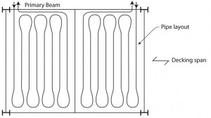
Figure 1: Typical plan view of individual heating pipe circuit for a floor Positioning of the pipes within the depth of the floor slab
Typical floor layout of heating pipes
The heating pipes are usually about 20 mm diameter and are laid in a single plane above the decking on a support system. The layout comprises a series of zig-zag circuits repeated across a floor, with the return pipe from each circuit led back to a manifold adjacent to the feed pipe, as shown in Figure 1.
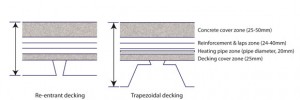
Heating pipes will normally be placed between the mesh reinforcement and the profiled decking. The suggested depth of the zones necessary to install the pipes (including any proprietary supporting system and the reinforcement) is shown in Figure 2. The minimum practical thickness of a composite floor with pipes installed is likely to be at least 150 mm, but is dependent on the depth of the decking.
Cross sectional properties of composite slabs
Until test evidence is available, it is recommended that a conservative view is taken when calculating the strength of the composite slab with embedded pipes: all concrete displaced by the pipes should be ignored. However, it is thought that the shear connection between the decking and the concrete will not be affected by the presence of the pipes because it relies on mechanical interlock; this interlock will be maintained, provided that the concrete can be compacted properly beneath the pipes. Clearly, pipes should not be grouped together in a way that compaction could be compromised – a minimum spacing between the pipes of the maximum aggregate size plus 5 mm, but not less than 25 mm, is recommended.
Cross sectional properties of composite beams
Bending resistance and stiffness
As with composite slabs, all concrete displaced by the pipes should be ignored when determining resistance. This means that when determining the bending resistance of the composite beam, the pipe area should be deducted from compression stress block in the concrete. Clearly, this is only necessary when the level of the pipe is within the compression zone in the concrete, and it is only relevant when the pipe is transverse to the axis of the beam. The pipe area may be ignored when calculating the composite second moment of area of the beam (for use in stiffness calculations).
Shear connection
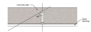
It is recommended that, when determining the shear resistance of headed stud connectors, the contribution from a stud should be ignored if the failure surface of the local compression zone around it is intersected by a pipe. The compression zone is illustrated diagrammatically in SCI-P300, Figure 5.5 and from experience of push-out testing carried out by SCI, the spread of the compression zone adjacent to a stud lies at an angle from the top of the stud to its vertical axis of about 60° down towards the decking, as shown in Figure 3. This would suggest that any pipe should be laid a clear distance from the stud of at least 1.75 times the stud height for the resistance of the stud to be unaffected by its presence. For nominally 100 mm long studs, a practical limit of 400 mm diameter circular clearance zone around the stud is recommended. (Strictly, since the potential failure zone occurs on the compression side of the stud, the exclusion zone only needs to be on that side but, for simplicity, a circular zone around the stud is recommended.)
In practice, this recommendation will mean that, for each pipe transverse to the beam, the adjacent the stud or pair of studs would be ignored. It is recognised that this could have a considerable effect on the design of beams for pipe arrangements where numerous pipes cross the beams. If the layouts cannot be arranged in a similar way to that shown in Figure 1, which avoids multiple crossings, it may be necessary to design the beams using non-composite properties. It is also undesirable to place pipes longitudinally to the beam in a way that the circular zone around the studs is intersected. Pipe layouts between beams, with single pipes across the beams only near the columns, may prove to be the most structurally efficient.
Normally, the number of studs on a beam is determined from consideration of the lower of the number required to meet the minimum degree of shear connection rules, (which is based on the span, yield strength and section geometry) and the number based on the force in the concrete to achieve the plastic moment of resistance. The calculation of the force in the concrete (to establish the moment resistance) is dependent on the effective area of concrete, which should not be reduced by the area of the pipe.
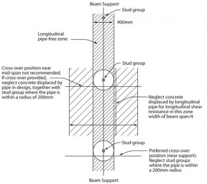
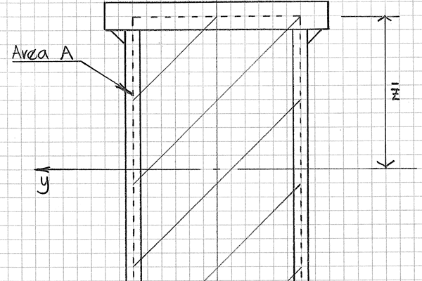
Figure 4: Recommendations for pipe positioning and implications for design for composite beams with 100 mm high stud shear connectors
Longitudinal shear resistance of the slab
In order for the full effective breadth of the concrete slab to be utilised for the composite resistance of the beam, it is necessary for the pipes not to affect the potential shear failure planes in the zones either side of the beam – i.e. the zones to the extremities of the effective breadth. The pipe arrangements in the slab between the beams would have an effect on any potential longitudinal shear plane according to the area of concrete displaced. This effect would obviously diminish for planes nearer to the edge of the effective breadth, where the applied longitudinal shear is lower, and could be zero even for pipes within the effective breadth if there is sufficient concrete and reinforcement to provide the necessary longitudinal shear resistance. Where pipe arrangements employ a single pipe (or a small number of pipes) transverse to the beam, there would be negligible effect on the longitudinal shear resistance of the slab, but pipes running parallel to the axis of the beam will have an effect. In the latter case the area of the pipe should be deducted when calculating the longitudinal shear resistance.
Summary
- Pipe layouts between beams, with single pipes across the beams near the columns, are likely to have the least effect on structural performance.
- All concrete displaced by pipes should be ignored for strength calculations for composite slabs and beams.
- The contribution from any stud to the shear resistance of beams should be ignored when pipes are within a radius of the 1.75 x height of stud (for nominally 100 mm long studs, say 200 mm radius).
- Minimum shear connection rules should be complied with for beams by analysing the required number of studs without the presence of pipes.
- Pipes should be located as shown in Figure 4. The 400 mm width of pipe-free zone is based on the use of 100 mm high stud shear connectors.
Contact: J W Rackham
Tel: 01344 636525
Email: advisory@steel-sci.com

