50 & 20 Years Ago
A forward looking concept in bridge design
 The problem is not an unfamiliar one: an interharbour bridge is to be built as part of an interchange between interstate highways in the United States – in Baltimore, Maryland, to be precise. Considerable investigation has been carried out and unusual thoughts have been forthcoming. The bridge envisaged consists of three decks at approximately the same level: two decks each with five lanes, the third having four lanes. Pedestrians would have rights of way through this third deck.
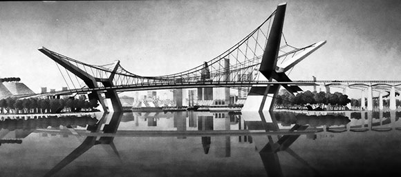
All decks would be of orthrotropic design, constructed of steel and be equipped with resilient asphalt driving surfaces: the decks to be supported by steel cables similar to suspension bridges, but in a very different manner. The design allows for criss-crossing cables in various planes, supported by Y-shaped abutments at each end of the bridge. Considerably less steel per sq ft is required than for a conventional bridge, bringing desirable economies. The decks are approximately 800 ft long terminating at the first concrete supports of the approaches.
The Y-shaped abutments are narrow and straddle only the middle deck: they are more economical to build than the more usual vertical towers but are less bulky than four towers situated at the faces of the three decks. Since they do not obstruct the view of the bridge at its entrance, not only does the approach to the bridge become more convenient but the abutments also add lightness and grace.
As the inclined planes of cables are attached to the outer decks only, the middle deck will be connected to the outer decks through the 16-ft space between them, with shallow struts at approximately 36ft on centres.
The bridge as envisioned solves two problems: extreme width (650 ft between abutments), and a 65 ft clearance underneath for almost the entire width. This maximum clearance is being achieved by utilising the system of cables incorporated which does not require stiffening trusses and permits the use of an extremely thin deck only 4 ft deep: this compares with 15ft in the case of a conventional bridge and 8 ft for a suspension bridge requiring stiffening trusses.
Many recent technological advances are embodied in the design. The basket suspension system is extremely rigid in all directions. An unusual feature is the concave cables which will be anchored to the ground. They pull down on the convex cables and provide rigidity to the bridge in all directions as well as stabilising it against vibration.
There have been very few innovations in structural systems of bridges in the last four decades. Any improvements have been confined to site construction or in variations of conventional structural systems. Of all the schemes studied and developed for this particular project, and there have been many including horizontal girders, arches, steel frames, shells and cable suspensions with concrete, prestressed concrete and structural steelwork, the one submitted has come nearest to satisfying the required criteria. Most others because of the significant depth of structural members did not offset the desired clearance under the bridge or clear sight view from the bridge. The only possible alternative design, other than cable suspension, that might satisfy the two requirements would be a thin concrete shell above the bridge from which the decks would be supported by vertical hangers. The shell would be structurally unique and aesthetically exciting but would be substantially more expensive than the design submitted.
The structural system for the bridge as described consists of components that have been widely applied in construction in recent years. An overriding consideration is that this bridge would employ one third of the weight of steelwork that would be required for the same span using conventional construction.