50 & 20 Years Ago
40 Years Ago: Separating the Mersey Tunnel
Taken from Building with Steel 1969
In 1935, when the Birkenhead to Liverpool Tunnel under the River Mersey (the Queensway Tunnel) was opened, the total number of vehicles on British roads was 2.6 million. By 1966 the figure had increased to 13.3 million. The amount of traffic wishing to use the Mersey Tunnel had increased in an even greater proportion and the vehicular traffic flow through the Tunnel during peak flow periods is restricted by the capacity of the Tunnel itself. This in turn results in the overloading and congestion of the approach roads which have to act as queueing reservoirs for Tunnel traffic. The main commercial shopping centre of Birkenhead is about a quarter of a mile away from the Birkenhead main entrance to the Tunnel, and town traffic is brought to a standstill as queues backing up from the tunnel encroach on this area. This occurs during morning and evening peak hours and summer weekends with the evening peak hours and summer weekends with the result that this vital town centre is obstructed with traffic for long periods.
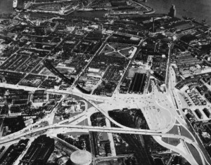
In 1965, Mr H. C. Oxburgh, BSc, C.Eng, AMICE, MIMimE, DipTP, MTPI (Borough Engineer and Surveyor to the County Borough of Birkenhead), drew up the scheme shown in the photo-montage of the project on this page, and now being implemented to ensure the free flow of traffic in the centre of Birkenhead. This proposal provides grade-separated relief roads to segregate ‘Tunnel only’ traffic from town traffic and incorporates two large marshalling areas or queueing reservoirs for the Tunnel bound traffic. Not shown in the photograph is the large number of underground obstructions complicating the implementation of the project. These include the local MANWEB electricity distribution system and 132 kV CEGB grid cables, high and low pressure gas mains from the adjacent gas woks, water mains, telephone cables (including the GPO’s London-Liverpool-Glasgow trunk services) and Rediffusion cables. Many of these services have had to be extensively re-routed. In addition there are four railway tunnels running under the site.
In September 1965 Consulting Engineers were appointed for the detailed design of the project and for the supervision of its construction. The design which they have developed for the elevated viaduct structures has been based on the use of composite steel-concrete box girder sections spanning over steel columns. This arrangement was chosen for several reasons. The single column configuration has certain obvious advantages in providing clearances to existing and future traffic lanes and railway tracks and other less obvious ones, such as reducing the intrusion of foundations into the underground services networks.
Furthermore, the clean lines so achieved, have aesthetic advantages not only in their contribution to the general appearance of the structure but also in avoiding the forest of columns that would ensue at bifurcation points if a twin post format were adopted. The span dimensions are mainly dictated by site requirements and range from 67 ft to 110 ft. The composite steel-concrete box girder arrangement adopted is of advantage where long spans to tight horizontal radii are necessarily involved and resulting in comparative ease of erection, aesthetically pleasing outlines and low depth span ratios.
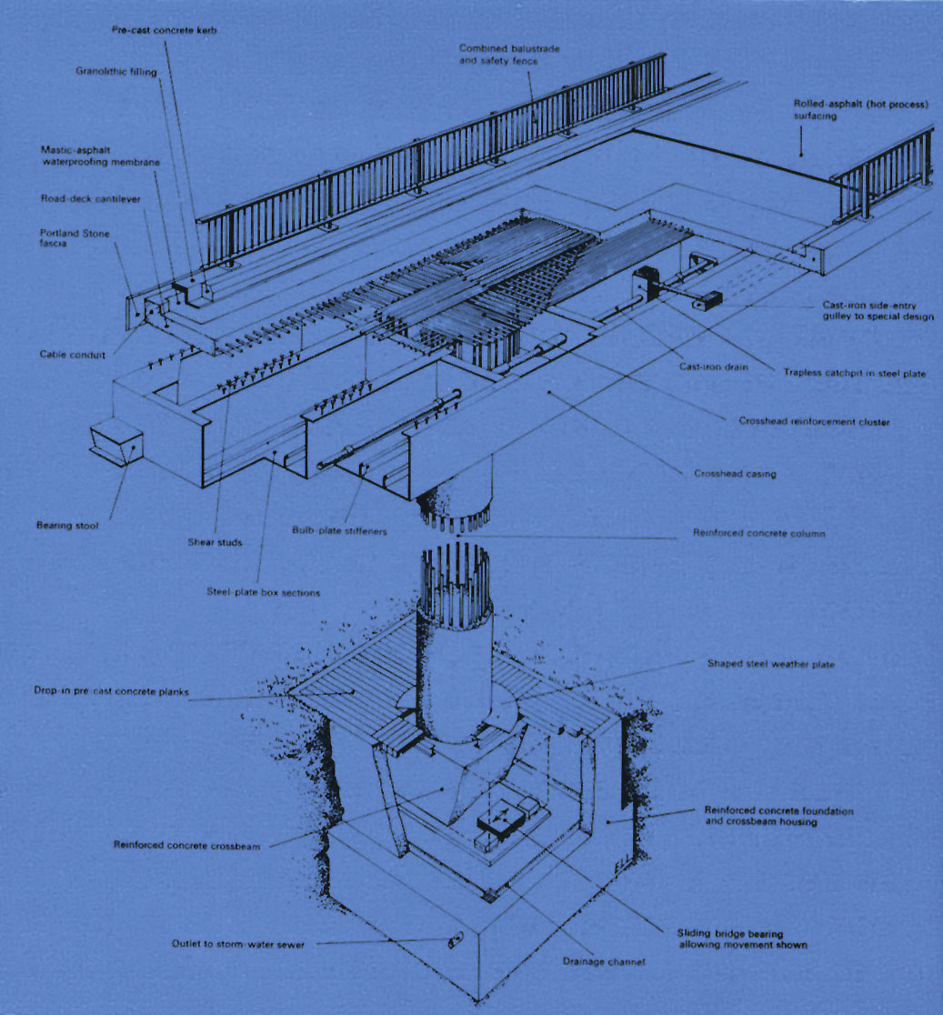
In order to limit the effects of temperature and stress movements the design was based on the cantilever – suspended span principle in which longitudinal portals, each with one fixed leg and one free leg, alternate with spans suspended with cantilever extensions to the portals. All longitudinal forces are taken by the fixed columns. The lateral stability of the structure is ensured by both the fixed and the free columns, the latter widening out at their bases to form cross beams, which sit on sliding ‘Rotaflon’ bearings. Other designs, using prestressed or reinforced concrete, were investigated at an early stage but it was found that although some of these alternatives would have resulted in comparable costs per square foot of deck area, other advantages weighed in favour of the adopted design.
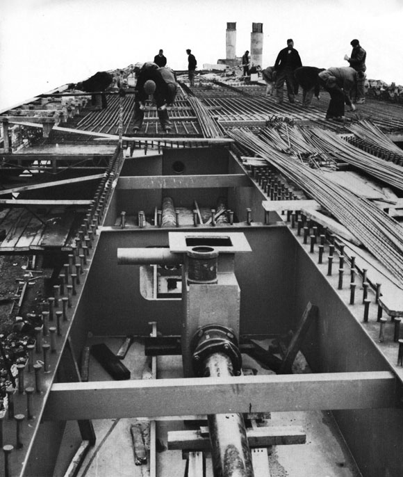
A solution was required for the junction between the columns and the beams of the portal spans, which would not encroach on certain critical clearances and in which the clean flowing lines of the structure were not interrupted. These requirements ruled out any form of external crosshead to the column and in the adopted design, the reinforced concrete column is cast integrally into the steel box as shown. The viaducts consist in principle of two or three cell box girders 12 ft or 18 ft wide respectively. The box girder acts compositely with the concrete deck slab (or with the reinforcement in the deck slab in areas of hogging moment), but at the crosshead the central webs are terminated at transverse diaphragms 5ft on either side of the column centre line. As this crosshead has to transmit longitudinal moments from the span to the column, the column reinforcing bars are continued up into the crosshead section to lap with bent down elements of the longitudinal deck reinforcement, the whole of the crosshead section being filled with concrete.
A similar reinforcement arrangement caters for the transverse and torsional moments which arise for the horizontal curvature and eccentric loading. The vertical loading normally carried by the steel box girder webs is transferred from the span sections into the concrete crosshead block by shear studs on the diaphragms and on the outer webs.
In order to verify the soundness of the design of the crosshead area of the structure, tests were carried out at the Imperial College of Science and technology on a quarter-full-size model illustrated on this page. These tests were made primarily to determine the manner in which loads from the steel elements of the structure find their way through the crosshead section and down into the reinforced concrete column. One hundred and twenty strain gauges, which were ‘read’ electronically, were used to record the distribution of stresses within the crosshead area under the various loading conditions imposed. Investigations were also made into the stiffness of the intermediate diaphragms and on the effect of introducing access manholes in the bottom flanges of the spans.
After the full series of tests to simulated working load values under a variety of loading conditions had been carried out, the loads on the model were increased to determine the ultimate factors of safety of the constituent elements of the structure. The basic interpretation of the results shows that the steel box girder section outside the crosshead was the weakest link but that even so a factor of safety of 2.65 existed at this position in the model.
The tunnel traffic sections of the viaduct system have been designed in accordance with BS 153: Steel Girder Bridges, to carry HA loading and checked for 37½units of HB loading. The town traffic viaduct has been designed to carry HA loading and checked for 45 units of HB loading. The various drafts of CP 117: Part 2, Beams for Bridges, were used for guidance in the design of the composite elements of the structures.
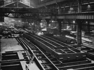
In general, because of the length of the spans (from 67ft to 110ft) and the width of the steel box girders (12ft or 18ft) the portal sections are each fabricated in a maximum of six sub-assemblies. The entire structure will be erected on trestles prior to making the site connections. The longitudinal joints in the span sections will be site welded and the transverse joints site bolted using high strength friction grip bolts. At the crosshead, the bottom flange splice and the lower part of the web splice utilize the rim plate type of joint while the ‘top flange’ splice is made by the steel reinforcement running over the joint.
Shop fabrication of the steel superstructure commenced in September 1967 and the first sections were erected in mid-December 1967. In all, some 1,700 tons of structural steelwork will be erected by December of this year.
Consulting Engineers – Brian Colquhon and Partners.


