50 & 20 Years Ago
Wagon Loading Station
In some ways these structures are not buildings, being essentially large plants with weatherproof covers. Nonetheless, they are very interesting and are described by Mr R. Wigley, Manager of the Projects Department of Butterley Engineering Co. Ltd. Three plants have been built but the emphasis is given to that at Redcar.
During 1973 Redcar and lmmingham Ore Terminals were brought on stream as part of BSC’s expansion programme and work was begun on a third terminal at Port Talbot. While this article deals mainly with Redcar the function of all three is very similar.
They are designed to handle large quantities of imported ore for stocking and inward transportation to inland steelworks. A complete installation includes port facilities, ship unloaders, conveyor systems to adjacent stockyards, stocking and reclaiming facilities and provision for onward movement of ore. These notes feature the train-loading facilities which have been designed to provide rapid loading of large tonnages of ore into merry-go-round train systems.
The purpose of the system is to control the flow rate of gravity-activated ore from storage bunkers into weigh hoppers, arranged to provide accurate repetitive weighing, and then into rail wagons. Differences in the types of ore handled at the three sites require variations in the equipment but they are broadly similar.

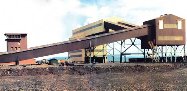
REDCAR TRAIN LOADING STATION
Specification
This called for the capacity to load complete trains in under 30 minutes where each train could consist of 15-21 rigid coupled 100T bogie wagons or 24-36 loose coupled 26T SVB wagons in rakes of 3 and 6 wagons respectively. The ore to be handled would range from fines, concentrates and pellets to 8in rubble ore. The moisture content could be up to 15 per cent and bulk densities could be between 110lb/cu.ft and 190Ib/cu.ft.
The design
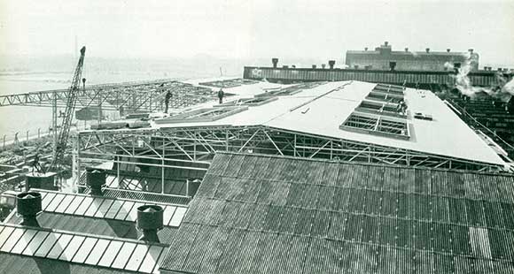
Holding bunkers
There are two lines of bunkers each with a capacity of 5000T based on ore at 190Ib/cu.ft. They are fabricated from mild steel and are built into a portal frame structure which spans the twin sets of rail tracks and each line includes six bunkers. These are filled from a conveyor system with shuttles which traverse them in either automatic or manual modes. Ore levels are monitored and the central control system automatically adjusts the shuttle traverse to obtain uniform filling of the bunkers. Three levels are specifically monitored. At the low level the operation of the vibrating feeders is inhibited. The minimum contents level is chosen to ensure that whole trains can be loaded without interruption and is set to allow for the rate of input while outloading is taking place. High level stops the reclaim system before full bunker level is reached. This prevents ‘hunting’ of the system and minimizes the effects of the reclaim system starting under full load conditions.
Discharge control is effected by a pair of hydraulically operated doors which regulate the flow of material on to twin vibratory feeders. The central control system determines the size of door opening depending on the characteristics of the ore being handled. Six weigh hoppers are freely suspended on tension load cells below each line of bunkers and they operate either in pairs or singly discharging 76 tonnes into bogie wagons or 38 tonnes in AVBs.
Should there be a power failure the weigh hopper bottom doors are automatically locked shut by an over centre self-locking linkage. The hydraulic equipment for the doors includes three interchangeable sets of pumping and accumulator systems. The nitrogen-charged accumulators have sufficient capacity to carry out one full cycle of operation in the case of an electrical power failure. Site welding was eliminated on all major connections by the use of high strength friction grip bolts. Each main column was designed to carry 950 tonnes and altogether 2,000 tonnes of structural steelwork have been used in the building and equipment.

Conveyors
A dual conveyor system is provided, 1,200mm wide, which runs at 2·25m/sec with each conveyor rated at 2,000T/hr. Two belt weighers are fitted in the conveyor system to monitor the feed rate to the bunkers.
Railway signalling and wagon positioning
The control equipment is designed to handle three types of train, the two described above and one consisting of 25½ tonne 2-axle ironstone hopper wagons, used half coupled and made up in lengths between 24 and 36 wagons. All three types are. headed by one three-axle locomotive. Loco-driver instruction is given by four aspect signals and these together with wheel sensers position the wagons. The sensers detect the type of wagons being handled and their spotted positions relative to the weigh hoppers. At each end of the loading area are air-operated retarders which apply external braking forces to the wagons to assist in obtaining a positioning accuracy of ± 6in, particularly with respect to the loose coupled wagons.
Weighing
Two independent sets of weighing equipment are installed. One controls batch weighing from the bunkers into the weigh hoppers while the other provides weighing in-motion of the wagons. The latter system feeds the control system with tare and gross individual wagon weights, the axle weights and whether 2- or 4-axle wagons are entering the system. Axle weights are monitored to determine the load distribution within the wagons and ensure that they are safely loaded. Weigh hopper batch requirements are programmed by determining the number of axles.
Dust suppression
Water spray systems under automatic control are provided at material transfer points. Furthermore the top surface of the ore within the wagons is sprayed to minimize ore losses during transportation.
Control system
While each of the main components of the plant has its own control system the various functions are co-ordinated through a central control logic system with control desk and mimic panel.
Loading procedure
Filling the bunker is an independent function and is not interlocked with the wagon loading except for the minimum contents level as described earlier.
To be filled a train enters the reception sidings where it waits until all is clear when the operator presses a train ‘accept’ button on the control desk. This changes the four aspect signalling from red to green. The train then moves into the loading area where, after receiving an amber light warning of ‘spotting’ position imminent, the driver stops it on the red light signal with the aid of the retarders. Any overshoot is indicated by a flashing red light when the train is backed up.
Once the wagons are correctly spotted and after a short delay for proving time the vibrators begin feeding the weigh hoppers. When the correct amount of ore has nearly been reached in the weigh hoppers the vibrators are switched to trickle feed for topping-up and the contents are printed out. When this is complete the ore is discharged into the wagons.
After a delay to prove the hoppers are empty the doors are closed, the signal is changed to green, the train moves off and the vibrators are restarted for another cycle. This procedure continues until the last rake is spotted and the number of wagons ascertained. Only the required weigh hoppers are then activated and the wagons filled. The train then leaves after it has been given clearance and its total weigh is recorded at the gross weighbridge on the way.
Interlocks
The system is fully interlocked and the three main locks prevent loading until the bunker contents are at a predetermined· level, stop the vibrators running while the weigh hopper doors are operating and vice versa and prevent any discharge from the weigh hoppers until the wagons are in position and proved.
From Building with Steel, March 1974