Projects and Features
Towering success

The sixth and final phase of the Broadgate redevelopment involves the use of structural steelwork to construct twin office towers, rising to 21 and 38 floors respectively.
FACT FILE
2 Finsbury Avenue at Broadgate, London
Main client: British Land
Concept architect: 3XN
Principle architect: Adamson Associates
Main contractor: Sir Robert McAlpine
Structural engineer: Ramboll
Steelwork contractor: William Hare
Steel tonnage: 10,000t
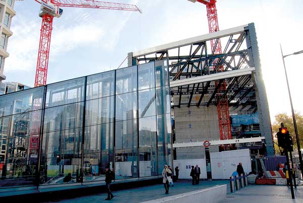
Located close to the City of London’s eastern boundary, the 10-year redevelopment of the Broadgate campus is into its final phase with the construction of 2 Finsbury Avenue (2FA).
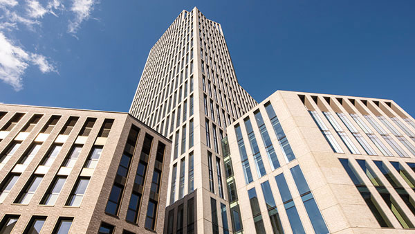
The biggest phase to date, on what is the capital’s largest pedestrianised neighbourhood, 2FA consists of dual office towers, sat on a 12-storey podium. The towers will top out at heights of 100m and 170m respectively, helping the scheme to deliver more than 75,000m² of workspace.
2FA will be an iconic addition to London’s skyline, as the towers will be instantly recognisable landmarks, characterised by innovative triangular patterns combining a solid and glazed sawtooth-shaped façade.
British Land has appointed Sir Robert McAlpine (SRM) as the main contractor, extending a partnership that has delivered previous Broadgate phases including 100 Liverpool Street and 1 Broadgate (See NSC January 2019 and April 2024).

Having also worked on previous phases, another team member is steelwork contractor William Hare, who is again bringing its fabrication, supply and erection expertise to the table.
Structural steelwork is playing a significant role at 2FA, as the steel-framed project aims to achieve the client’s sustainability goals, which include targeting net zero carbon in construction and operation, as well as a BREEAM ‘Outstanding’ rating.
“The steel frame is very efficient and lean,” says William Hare Project Director, Francisco Loureiro. “A significant carbon saving is being realised by using high-strength sections wherever possible.”
Delivering another carbon saving, approximately 90% of the steel sections have been sourced from Electric Arc Furnace production facilities. This material is considered to be much greener and more efficient in terms of energy consumption for the production process.

Work on the project began with the demolition of two 1980s-built office blocks. With the site cleared, new foundations were installed, which consisted of a series of mono-piles, up to 50m deep. The piles had to be installed around existing foundations and this required a thorough survey of the plot in order to make sure there were no clashes.
A new and deeper basement, covering the entire 100m × 40m footprint of the site was also excavated. In order to speed up the construction programme, a top-down procedure is being employed, whereby the basement is being completed (work that includes the installation of 12m-deep steel plunge columns) below an installed ground floor slab, while above, the steel frame is simultaneously being erected.
With numerous trades and activities taking place at once, coordination between the various teams is a key element for the project.
Above ground, the steel erectors are sharing the site with the concrete contractor installing the two cores. To allow each trade to operate independently, the steel erectors have use of the site’s three tower cranes, while the concrete team have their own cranes positioned on the top of each core.

Space is at a premium on the site, with little or no room for material storage. Steelwork is delivered either via Sun Street or Wilson Street, along the site’s north and western boundaries, and is placed adjacent to the erection area.
Highlighting the site’s constraints, the eastern end of the plot does not offer a suitable location for a tower crane as the boundary sits close to some existing buildings. To solve this challenge, a steel-framed gantry, weighing more than 50t and connected back to the east core, cantilevers out over Sun Street supporting one of the project’s tower cranes.
The taller and slenderer, 38-storey east core, was the first to begin construction. A few months later, the steel frame, which derives its stability from the cores, was able to begin its erection process in this area, following on behind the concrete workings above.
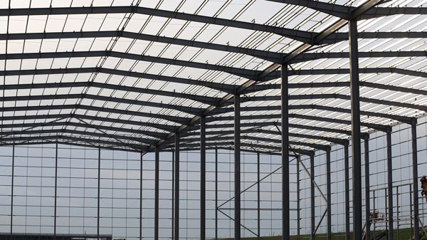
The steel frame is predominantly based around a regular column grid pattern, as Ramboll Director Ollie Wildman explains: “The efficiency of the design is represented in the lack of heavy transfer structures and the seamless intersection arrangements where the podium and towers meet.

“The podium and towers have a 12m x 9m grid, while the angled tower façade lines are designed carefully to intersect with half a bay to minimise columns.”
This design creates flexible floorplates throughout the scheme, with minimal internal columns. Cellular beams that accommodate the building services within their depth are used throughout the project. These beams support a metal decked composite solution for each level above the ground floor slab.
Office space is a valuable commodity and in order to increase the size of each floorplate, every elevation cantilevers out, beyond the foundations, by up to 6.6m.
This is created by a series of raking columns that start at first floor and extend to the underside of the fifth floor. The angle at which the column’s rake varies depending on the elevation, with the north side of the building having the widest cantilever.

The perimeter columns for floors one to four are hung from the underside of the fifth and once the cladding is complete, the raking columns will be hidden from view and each façade will have a right-angled overhang above the pavement.
“The project design went through a number of iterations, during a Pre-Construction Services Agreement period with William Hare and SRM coordinating. Raking members were chosen to create extra floorspace as we needed to keep all of the columns within the project footprint, especially along Sun Street where there are a number of underground services,” says SRM Project Director, George Amy.

As well as offering plenty of Grade A office space, 2FA will also provide tenants with a range of amenities including green terraces and landscaped areas. The largest of these will be a winter garden, located on the roof of the podium between the east and west towers.
A glazed hybrid steel and timber frame, will semi-enclose the winter garden, offering workers a break-out and meeting space for all seasons.
The steel erection programme is due to finish at the beginning of 2026, while the entire 2FA project will complete in June 2027.

Sloping columns
The 2 Finsbury Avenue project makes use of sloping columns as part of its design. Max Cooper of the SCI offers a few thoughts on the benefits of their use and structural design issues to consider.
In inner-city projects, developers and architects face a common challenge: maximising usable floor space within a constrained site plot. They must also strive to meet planning requirements that encourage developers to contribute to the public realm by setting back from site boundaries, further restricting the ground floor footprint. Sloping or raked columns can present an elegant structural solution to this challenge, allowing the building footprint to grow, as the building rises from its base. Unlike traditional transfer structures, which typically require significant structural depth and associated floor-to-floor height penalties, sloping columns can achieve the desired spatial expansion while maintaining efficient floor depths.
While the implementation of any load transfer system carries important cost and carbon implications, the gains in both gross and lettable area often justify these considerations, particularly in high-value urban locations. Their design, however, is not trivial and engineers should carefully consider the issues that arise through their use.
At the point a column slopes, a significant lateral force is introduced to the floor level which is proportional to the column load and the angle of slope. The larger the change in angle, the larger the force that must be resisted. The designer should have a clear understanding of the magnitude of this force and a clearly designed and detailed load path for all the members and connections that are affected.
These in-plane forces must ultimately be resisted by the building’s lateral stability system. For most composite buildings, this will be a concrete shear wall, and therefore care must be given to the design of the embedded plate connections for these load-carrying members. Reference can be made to SCI guide P416 The Design of Cast-In Plates for discussion of the design of these connections in the presence of axial force.
Where the lateral force does not directly align with the building shear walls, the forces will be required to be transferred within the plane of the slab. One method would be to use in-plane bracing elements, the location of which must be coordinated with building services.
The lateral loads may be carried by floor framing beams or dedicated tie members. Where floor framing members are used, care should be taken to ensure the axial force is considered in both the design of the beam, and any web openings where the loss of net area of the web will have a pronounced effect. The axial force may also impact the design of shear connectors in composite slabs.
Finally, the axial forces must be accounted for in the connection designs. Where these connections are designed by the steelwork contractor, it is essential that the axial force demands are clearly communicated on the design documentation.