Technical
The development of design rules for restrained columns
Following on from the previous two articles, David Brown of the SCI looks back at the development of design rules for restrained columns. Looking at the work in the 1950s and 1970s reveals the background for many of the features found in today’s design standards
The June and July/August articles on restraints around portal frames encouraged a closer look at the rules defining the resistance of restrained columns, making the link between the current rules in BS 5950 and BS EN 1993-1-1 and the salient technical papers published in the 1970s. The work on columns with restraints refers back to earlier rules covering unrestrained columns and unadopted recommendations to modify BS 449, the design standard of the time.
Early research
The most significant papers covering restrained columns are Design of columns restrained by side-rails1 and Failure of columns laterally supported on one flange2, both by Horne and Ajmani, published in 1971 and 1972 respectively, and the record of the associated discussion published in 19733. The authors and contributors include a number of very well-known names in the steelwork world. Professor Horne OBE is a co-author of Plastic design of Low-Rise Frames4 which used to be the definitive work in the UK on portal frame design and detailing. A contributor to the discussion was Dr Morris, co-author of the aforementioned publication, and forever known by the shear stiffener which takes his name. Other contributors to the discussion include Dr Wood, known for the effective length curves found in Appendix E of BS 5950, Professor Nethercot, widely known for most things in steelwork and Mr Needham, who is known for his work with CONSTRADO, the forerunner to SCI.
Dr Ajmani was the Chief Design Engineer for the Tata Iron and Steel Company of Jamshedpur, India. Clearly Dr Ajmani would not know that decades later, his company would buy Corus, previously known as British Steel, Jaguar Land Rover and Tetley Tea – and be so significant in the UK steel industry.
The 1971 and 1972 papers present the rules for members restrained on one side only – the tension flange, as typically found with a portal frame column. The work undertaken by Horne and Ajmani leads directly to the stable length rules found in Section 5 and Annex G of BS 5950. In turn, this leads directly to the rules found in BS EN 1993-1-1 section BB.3. Some 50 years later, current design rules depend on this research from the 1970s.
Figure 1: Effective lengths of stanchions according to BS 449 (Figure 15)
The discussion of the paper is perhaps most interesting. At the time, the UK design standard was BS 449. This standard offered guidance on the effective length of “stanchions” in Appendix D, and proposed that if a stanchion was restrained by side rails, the effective length factor in the minor axis was 0.75L. No limitation was placed on the maximum spacing of side rails – the effective length was always 0.75L. Figure 1 (Figure 15 from BS 449) is interesting in that the side rails are angles, and are drawn as a considerable proportion of the stanchion depth – around 50%. This is quite different to details found today.
A Professor Bryan was moved to comment that “as Sir John Baker once said, the effective length concept is most unsatisfactory in that one takes the length of a column and then multiplies it by a factor which very much depends on what you had for breakfast”. Professor Bryan was complimenting Horne and Ajmani for their contribution in advancing the guidance. The work of Baker et al is discussed later in this article, though Baker himself correctly credits a Mr John Mason with the original quote.
Another contributor, Mr Dwight, noted that “it will at last be possible to take account of the restraint afforded by sheeting rails connected to the tension flange”. Mr Dwight also commented on “the practice sometimes adopted of bracing the sheeting rail back to the inner flange of the stanchion, thereby supposedly providing restraint to the compression flange”. Mr Dwight appears to be sceptical about the effectiveness of the system commonly employed nowadays. Mr Dwight assumed that there was “negligible advantage in doing this because of the great flexibility of the sheeting rail”. Professor Horne proposed verifying the relative stiffness of sheeting rail and restrained member – the checks appear in the SCI publications on portal frames with the recommendation that the verification is important when the member size starts to be disproportionate compared to the side rail.
Dr Morris recalled previous practice (he referred to the mid-1950s) and the “relatively simple calculations one used”. He noted that “it would seem that as our knowledge of structural behaviour is extended, the design process is refined and becomes complex, and it may be the case in the near future of reverting back to simple elastic design”. Although Dr Morris was apparently enthusiastic about elastic design, some ten years later he collaborated with Professor Horne to publish the definitive guide on plastic design of portal frames4. Since 1970, the design process has become ever more complex, frequently reliant on computer aided analysis and member verification by software, rather than the simplicity Dr Morris suggested.
The 1970s were clearly a significant time for the development of the design rules for portal frames. In 1979, Professor Horne collaborated on a further paper considering the stability of haunched members5. The design rules for haunched and tapered members in Section G of BS 5950 follow from this paper, and from then were “translated” into Eurocode nomenclature in Section BB.3.2 of BS EN 1993-1-1. Eurocode expressions such as BB.14 and BB.16 (and their equivalents in BS 5950) can be immediately recognised in the 1979 paper.
The reference to “Point A”, still used today, as the all-important junction between the bottom flange of the haunch and the inside face of the column is found in this paper, as illustrated in Figure 2 (Fig 1 from Horne et al)
Figure 2: “Point A” – where inner flanges meet (Fig 1 from Ref 5)
The steel skeleton
The comment by Professor Bryan referring to Sir John Baker moves us back another step to the early 1950s and the two volumes of The Steel Skeleton6,7. Volume 1 covers “Elastic Behaviour and Design”. Volume 2 covers “Plastic Behaviour and design” and perhaps it is no surprise that a co-author of volume 2 was Professor Horne – described as “one of the leading protagonists of plastic design”.
Both volumes are worth reading, containing some really interesting history. Volume 1 looks back further to 1929 when an investigation was undertaken to investigate the application of modern theory to the design of steel structures. This review considered practice in the UK, New York, Germany, France, Spain, Prussia and Belgium. The live loads to be designed for in different countries varied, as they did in various UK cities. Edinburgh and Glasgow agreed that halls, schools and churches must be designed for 180lb per sq.ft, (8.6 kN/m²) whereas Newcastle was content with 112 lb per sq.ft (5.4 kN/m²). Perhaps children and worshippers were not so socially distanced north of the border.
Volume 1 also records the live load reductions that were allowed in various countries, linking to the reduction factors we find in modern codes.
The significance of the loaded area reduction is also evident in the intensities of loading surveyed. Who would want to work in a (presumably claustrophobic) small finance company, when the loading was measured at 11 kN/m², compared to a structural engineering company at 4.5 kN/m²? However, when measured over a larger area, the situation is more comfortable; the loadings become 0.9 and 0.6 kN/m² respectively. Over a larger measured area, “consulting engineers” (as opposed to “structural engineers”) fare the worst at 1.7 kN/m². The survey also noted that concentrated loads, such as fire cabinets and safes needed special attention – another principle found in our modern loading codes.
Of equal interest in Volume 1 are the tests undertaken on real buildings. For one building, a hotel under construction by Dorman Long, it was suggested that a few platoons of soldiers from a nearby barracks could have been used to provide a well-distributed load. In the event, point loads were suspended from the beams. Strain gauge readings were affected by the riveting operations – a hazard not experienced today. A summary of the findings is that the measured effects in beams and stanchions were not as expected. Professor Baker described the behaviour as “radically different from that assumed in the design methods in common use”. One key difference was that the riveted connections were relatively stiff, making the frame behaviour more like a rigidly jointed frame than a pin-ended arrangement. It is worth remembering that designers are modelling loading and modelling the structure and its response.
The Steel Structures Research Committee produced “Recommendations for Design” based on these studies, which was essentially a semi-continuous design method, recognising the stiffness of the connection types used at the time. Unsurprisingly, the connections had to be classified (based on the detailing) – which was associated with the connection stiffness. We might reflect on the current guidance in BS 5950 that the detailing of the connections must be consistent with the assumptions made in the frame analysis, and the explicit requirement in the Eurocode to classify connections and allow for connection stiffness if the effects are significant. This is the same principle advocated in the proposed design method some 90 years ago.
The proposed design methods, published in 1936, were complicated. Baker comments that despite the constructional steel industry paying for the research for a period of 7 years “neither the industry itself nor consulting engineers generally felt any enthusiasm for the outcome of their labours”. Baker noted that “whatever criticism could be levelled at the method of design which had held the field for nearly fifty years, it certainly had the merit of simplicity; in fact it would be difficult to imagine anything simpler”. Baker also noted that the recommended procedures were laborious, and there was “no advantage that the average client would appreciate”. The orthodox method of design was shown to be safe, if quite conservative in some cases.
Wartime regulations
Once war broke out, steel was a very important commodity. A wartime amendment was made to BS 449 which increased the permissible stresses by 25%. Baker notes that “this earned the taunt that the engineer had discovered that steel was stronger in war than in peace, whereas all he was admitting was that greater risks had to be taken in wartime”.
In 1939, a recommendation was made that for government buildings, design should be based on the “more exact design methods” proposed by the Committee, but Baker notes “there is no evidence that this last wise recommendation has ever been acted upon”.
Holding nothing back!
In 1943, BS 449 was revised, still not embracing the more exact methods. One senses a degree of disappointment when Baker notes “the third revision…. owes nothing to the tests of existing buildings and the other resources… except that it has achieved almost all the economy possible in beams without bothering to define the vital end-connections to be used”. He suggests it perpetuates “a design method which neglects almost every effect but axial load and can only be defended on the score of expediency”. He does not spare his criticism – the method which was originally adopted as “an empirical method well proved by years of use to be safe… has been changed in a haphazard way unjustified by practical experience or the results of scientific investigation”. The method which so frustrates Baker is the assumption of nominal moments due to beam end reactions 100 mm from the face of a column – a method still loved in the UK found in clause 4.7.7 of BS 5950 and available to Eurocode designers via NCCI.
Baker concludes that further economy was certainly possible and that too much attention should not be paid to the complexity of the proposed design method “for it does less than justice to the abilities of steelwork designers”. Some 70 years later, perhaps we are on the advent of embracing semi-continuous design, being armed with numerical methods and software that will determine the stiffness of connections and software which can include connection stiffness in the frame analysis.
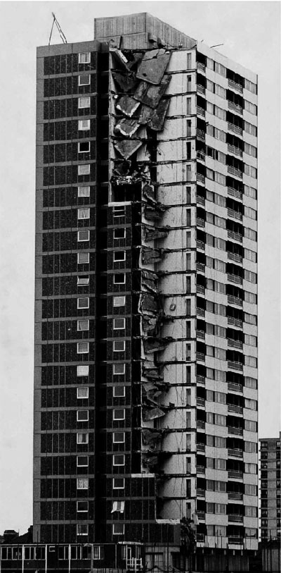
Figure 3: Ronan Point
Lessons from the war
Appendix B of Volume 1 reports on multi-storey steel frames subject to air attack. The appendix notes that it also shows what happens when these structures are subject to conditions of overload.
Of interest is the comment that “the floor (construction) which can best tie the members of the main frame together is to be preferred”. Today, we would discuss the subject under “the avoidance of disproportionate collapse”. Baker notes that “hardly ever does progressive collapse take place”, unless “the explosion caused failure of certain beam-to stanchion connections” (on the façade) “and allowed the external wall framework to move outwards, when a certain amount of collapse ensued”. Today, we would recognise the need for connections to not only carry the vertical shear, but also the tying forces to avoid exactly this problem. The appendix also makes recommendations about the layout of beams, which we would recognise as the arrangement of horizontal ties. Despite these clear recommendations, the disproportionate collapse at Ronan Point in 1968 (Figure 3) is usually noted as the catalyst for the modern tying rules, perhaps because the risk of blast from high explosive ended in 1945.
Conclusions
Many of the features of our modern codes have their roots in work completed many years ago – some expressions are precisely those proposed over 50 years ago. That original work was hugely significant, influencing much of what we do today, from loading to resistance calculations. Perhaps the tools that structural engineers now have available will finally facilitate progress from the empirical methods which Professor Baker described as “almost entirely irrational and therefore incapable of refinement”.
To appreciate something of the background and reasons for certain requirements must always be helpful. As Professor Baker notes: “it is important that the steelwork designer should not become a technician blindly applying irrational rules. He can only escape from this role if he has the information on which he can base better rules”
1 Horne, M. R. and Ajmani, J. L.
Design of columns restrained by side rails
The Structural Engineer, August 1971
2 Horne, M. R. and Ajmani, J. L.
Failure of columns laterally supported on one flange
The Structural Engineer, September 1972
3 Failure of columns laterally supported on one flange; Discussion
The Structural Engineer, July 1973
4 Horne, M. R and Morris, L. J.
Plastic design of low-rise frames
Collins, 1985
5 Horne, M. R. Shakir-Khalil, H. and Akhtar, S.
The stability of tapered and haunched beams
Proceedings, Institution of Civil Engineers, Part 2, September 1979
6 Baker, J. F.
The steel skeleton, Volume 1, Elastic behaviour and design
Cambridge University Press, 1954
7 Baker, J. F; Horne, M, R; Heyman, J.
The steel skeleton, Volume 2, Plastic behaviour and design
Cambridge University Press, 1956