50 & 20 Years Ago
The Congress Theatre Eastbourne
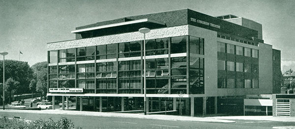 From Building with Steel November 1964
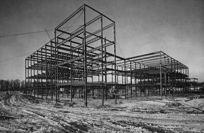
The steelwork for the Congress Theatre is interesting on account of the intricate and unusual detailing which is not normally encountered in structural steelwork. The three principal sections of the theatre in which steel is used are the auditorium roof, the backstage area and the restaurant. The restaurant in particular necessitated workmanship of the highest quality which was maintained throughout by the steelwork contractor.
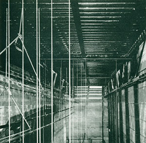
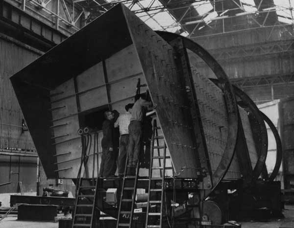
Backstage trusses showing bolted connections, stage grid supporting scenery and backcloth, vertical joists forming rear wall.
Detail backstage showing rear truss, fly gallery, stage grid and vertical joists.
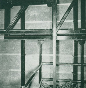
Auditorium roof showing truss, bolted connections, transverse bracing, purlins and angles supporting false ceiling.
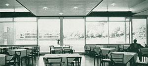
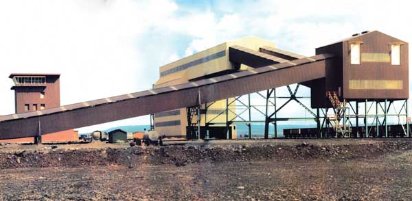
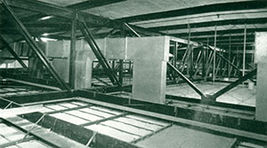
Restaurant with rectangular hollow sections as columns, channels and angles as fascias.
Whilst reinforced concrete was used for the general structure of the theatre on account of the varied spans and heavy loadings which had to be accommodated in the flat slab design envisaged by the architect, structural steelwork was selected for the roofs and restaurant as it was considered more economical for both the long spans with light loading and the less stringent fire precautions required.
Four trusses span the longitudinal direction over the auditorium, this span of 95 ft was chosen in lieu of 72 ft transversely so the weight of the roof would counter the overturning of the balcony. Spanning the trusses in this direction also assisted the provision of simple trunking for the ventilation system, particularly by incorporating all the transverse bracing in a vertical plane between the inner trusses only, thus giving the maximum amount of clear space in each outer section. The main top and bottom members of the trusses consist of two No. 8-in by 4-in angles, 4 inches apart, so that the verticals, 4-in by 3-in joist sections could be welded between them. The diagonals varied from 5-in by 3-in angles to 3-in by 3-in angles depending on the loadings.
6-in by 3-in purlins at 6 ft centres span 18 ft between the trusses, the slope in the roof being made by supporting the purlins at their top and bottom flanges respectively. The tank and machinery room extending for the whole width of the auditorium is suspended directly from the trusses by four steel hangers. The false ceiling which in a theatre tends to be rather heavy is suspended off 5-in by 3-in angles spanning between the bottom members of the trusses. At the proscenium end of the auditorium, in addition to the false ceiling, a sound baffle, loudspeaker system and maintenance walkways are suspended requiring larger supporting angles.
Initially the trusses both backstage and over the auditorium were specified to be all welded. Due to the restrictions as to access, particularly around the auditorium, the steelwork contractor was granted permission to fabricate the trusses in sections which would facilitate the use of the main contractor’s tower crane situated in the centre of the auditorium. A rise, to offset an anticipated deflection of one inch, was introduced by prebending the top and bottom members of each truss section and by raising the scaffolding. All site connections were made by using load indicating high strength friction grip bolts as this provided an easy way of checking the correct bolt tensions.
Backstage, three trusses span 65 ft transversely between the two flank walls of the stage tower and are supported on specially designed steel shoes bolted to the concrete walls. The trusses are at 13-ft centres and are 7 ft 9 in deep overall. The top and bottom members consist of two No. 5-in by 3-in angles with the verticals 4-in by 3-in joist sections again welded between them, all the diagonals being 3-in by 3-in angles. The rear wall of the stage tower is formed by 7-in by 4-in joists at 6-ft centres carrying woodwool slabs fixed with U bolts. These upright joists span 26 ft from the main roof level to the top chord of the rear truss, the connection at the upper level being a sliding joint to enable the truss to deflect independently. The roof purlins are 5-in by 3-in joist at 6-ft centres and the haystack lantern consists of frames at the same centres made out of 5-in by 3-in joist sections.
In addition to supporting the fly gallery the trusses support the ‘stage grid’. This is an intricate mat of steelwork, the function of which is to assist the moving and supporting of the stage sets, etc. Consequently it is designed for horizontal thrusts as well as for vertical loadings. The main members of the grid are 10-in by 3-in channels, the secondaries being 7-in by 3-in channels above which are laid 3-in by 1½-in channels at 6-in centres.
The link restaurant between the existing Winter Gardens and the Congress Theatre required maximum amount of circulation space between supports. There was also an architectural requirement to expose as much of the structure as possible on the elevations. A steelwork design was evolved using shallow trusses, rectangular hollow sections as columns and channels together with angles as fascia elements. Each truss spans 36 ft and is 2 ft 3 in deep overall. Interest is added to the roof by alternate bays being at high and low levels respectively. The 6-in by 3-in purlins span 13 ft being supported on the top and bottom members of the trusses.
The problem of an 18-in deep smooth face fascia in steel was overcome by bolting together a 12-in by 3½-in channel and a 6-in by 3-in angle. Prior to bolting, an epoxy resin was applied to the joint faces and after setting, the excesses were ground off, thus providing not only a smooth face but a waterproof joint. The trusses were supported by 5-in by 2½-in channels welded onto the backs of the external 5-in by 5-in columns. These channels also served to support the fascias which were bolted to the sides of the channels. Figure 1 clearly shows the intricate detailing which was required.