Projects and Features
Steel design stacks up
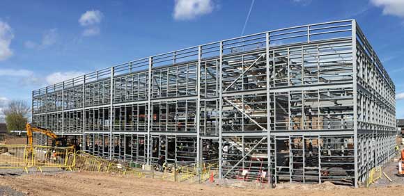
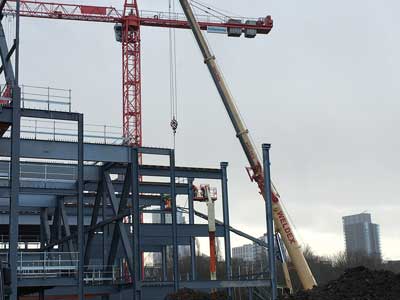
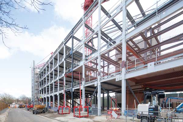
The new steel-framed leisure centre takes shape
Structural steelwork has provided the required efficient design and column-free spaces for a new leisure centre and an academy in east London. Martin Cooper reports.
FACT FILE
Britannia Leisure Centre and City of London Academy Shoreditch Park
Main client: Hackney Council
Architect for Britannia Leisure Centre: FaulknerBrowns
Architect for City of London Academy: Fielden Clegg Bradley Studios
Main contractor: Morgan Sindall Construction
Structural engineer: BuroHappold Engineering
Steelwork contractor: Severfield
Steel tonnage: 2,200tForming part of a multi-million-pound scheme that will transform a large swathe of land bordering Shoreditch Park in east London, the construction of a new leisure centre and an academy are providing proof that steel construction does stack-up when an efficient design is required.
Both buildings are using a steel-framed design to accommodate numerous facilities within a constrained footprint. The leisure centre has a variety of column-free areas, some of which are double-height and triple-height zones, each positioned on top or adjacent to each other, like a collection of different sized boxes.
“The leisure centre is replacing an existing facility and is being built on land previously occupied by tennis courts. It was important the new centre did not exceed the available footprint and encroach into the adjacent park,” explains Morgan Sindall Construction Project Director Lee Askey.
“The best option was to employ a design where the numerous sport and leisure facilities were stacked-up within the building.”
Meanwhile, on an adjacent plot, a similar design philosophy has been employed for the City of London Academy Shoreditch Park (see box below).
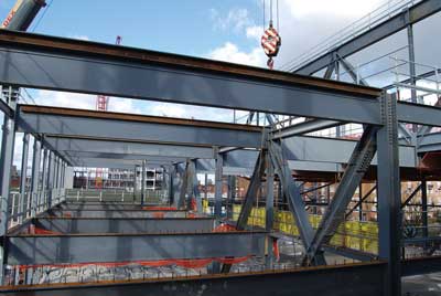
The leisure centre contains a number of open-plan column-free areas on each floor.
Cut-out image showing how the leisure centre stacks up. In the picture are the main pool and the flume zone.

Model showing the leisure centre’s truss arrangement and the long beams spanning the main pool.
The lower of the two trusses helps create the sports hall’s column-free space
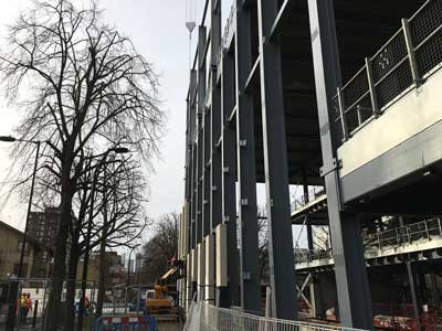
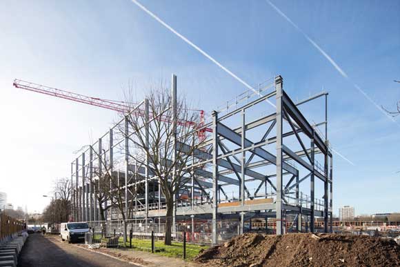
The eastern elevation of the leisure centre houses a triple-height space for the flume
The four-storey 11,500m² leisure centre’s design includes a triple-height colonnade, which runs along the main façade. It will usher customers into the facility’s entrance foyer. The ground floor will also house the centre’s wet area that consists of a six-lane, 25m-long main pool, 20m-long learner pool, a toddlers’ pool and a leisure water pool with a flume. There are also changing rooms and a crèche.
This floor level is where the building’s steel frame starts, as it is sat atop a concrete basement that houses the pool’s associated plant equipment.
The majority of the ground floor facilities are housed in large column-free areas that have different floor-to-ceiling heights, which do not align with the floors above. Consequently, the first and second floors do not cover the entire structure’s footprint as the main pool is a double-height space and takes a portion of the floor above, while the flume zone is a triple-height space intruding into both the first and second floors.
Accommodated on the available space of the first floor there is a six-court sports hall, two spin studios and four squash courts, all of which are further double-height spaces, and consequently they eat into the second level.
So, with less floor space than the levels below, the second floor only accommodates a new 250-station gym and changing rooms.
The uppermost level (three) is the roof, and this has two outdoor five-a-side football pitches and two tennis/netball courts. These areas are surrounded by a series of 8m-high galvanized posts that will support a netting system to enclose the playing areas and keep balls from being kicked or hit off the building’s roof. As well as these outdoor zones, the fourth floor also contains an indoor dance and martial arts studio and further plant rooms.
With so many different sized spaces within one single structure, a great deal of vibration analysis was undertaken to determine the best structural design for the leisure centre.
“Steelwork supporting 400mm-thick precast flooring planks was chosen as the best method to dampen any potential vibration issues between the various areas of the building,” explains BuroHappold Engineering Partner Angus Palmer.
“Deflection and dynamics also drove the size of each steel member as well as the orientation of the bracings.”
Consequently, there are a number of large steel elements within the leisure centre’s frame. The heaviest individual elements are a series of 20m-long × 1.8m-deep plate girders, each weighing 23t, that span and form the main pool area’s column-free space.
Another series of substantially-sized beams spans the first-floor sports hall and squash courts, forming part of the structure’s roof. The required 27m-long clear span is created from a series of two beams, 18m-long and 9m-long, which were spliced together on-site to form the overall span.
Helping to absorb the loadings from the various spaces within the structure are a couple of large trusses, positioned within the middle of the building.
The lower of the two trusses is two-storeys high and positioned at first-floor level, adjacent to the sports hall. It facilitates the column-free space of the sports hall and transfers floor loads over the training pool, which is directly below.
Measuring 28m-long x 10m-high and weighing 65t, the truss was erected piece-small, in individual sections, using a temporary trestle to support the bottom boom, while it was stabilised with temporary bracings back to the perimeter column bases.
The higher upstand truss sits at third floor level and splits the span above the sports hall, allowing a beam depth which maintains the clear height requirements of this space.
The upstand truss also forms the boundary for the central corridor; creating a physical threshold between the tennis courts and the circulation at the uppermost level three.
The truss is 35m-long × 9m-high and weighs close to 60t. It was assembled on site on temporary trestles, which were supported by the lower truss. Once fully assembled, it was installed to its final position via a tandem lift using two 500t-capacity mobile cranes.
The new Britannia Leisure Centre is due to open in spring 2021. The adjacent existing facility will then be demolished, making space for a residential element of the overall development.
 New Academy for London
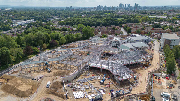
Adjacent to the existing leisure centre, a brand-new school, known as the London Academy Shoreditch Park is under construction on what was the centre’s car park.
The five-storey steel-framed academy will on completion provide 1,140 secondary and sixth form places to help meet demand in Hackney.
The steel frame is approximately 30m-wide and 100m-long, and based around three full-height atriums located along the structure’s length that provide circulation and break-out space.
 Stability is provided by concrete cores positioned at either end of the building, while a movement joint splits the structure in half with a double row of columns positioned midway along the length.
As well as the atrium voids the academy also features a sports hall located on the first floor, above some ground floor classrooms. Similar to the design procedure conducted on the leisure centre, a vibration analysis was carried out. Similar to the leisure centre, it was decided that steelwork supporting precast floor planks would be the best option for this building as well, in order to dampen any vibration issues.
The sports hall is a triple-height space, extending up through the three floors of the school, to the underside to the fourth floor. Spanning the hall is a series of 19m-long girders that weigh 6t each. As well as forming the sports hall’s roof, the girders also support two outdoor Multi-Use Games Areas (MUGA) located on the fourth floor.
The academy’s classrooms are predominantly located along the northern elevation and are formed with a regimented column grid pattern with perimeter columns spaced at 3m centres.
In order to maximise the available floor-to-ceiling heights in the classrooms and corridors, a series of bespoke trusses that accommodate all the services has been fabricated and installed by Severfield. The trusses are generally 10m-long × 1.4m-deep and weigh 10t each.
The academy is due to open in time for the autumn term of 2021.
Movement joints
Movement joints in buildings are introduced to solve one set of problems and introduce another. Richard Henderson of the SCI discusses some of the issues.
The structure of the City of London Academy Shoreditch Park is a steel frame of length 100 m with concrete cores for stability at each end. SCI publication P070[1] discusses the issue of expansion joints in steel-framed buildings in Chapter 7. The options available to the designer are to either design for the loads resulting from changes in temperature on a structure, or relieve them. The effects of the temperature change ΔT (thermal strain = ΔTα; thermal stress = ΔTαE where α = 12 × 10-6 per Kelvin for T < 100°C) for a theoretical temperature range of -5 to +35°C or say ± 20 K, are a strain of ± 2.4 × 10⁻⁴ or an unfactored stress of 50.4 MPa when the movement is fully restrained
Examination of Table 7.1 in P070 shows that the maximum recommended spacing of expansion joints in steel-framed commercial buildings of simple construction is 100 m. The movement joint in the middle of the 100 m length of the Academy building therefore requires a movement allowance of about twice 50 × 10³ × 2.4 × 10-4 mm or 24 mm. If no joint were provided, the longitudinal members would theoretically experience a stress because of restraint by the concrete cores from the maximum temperature change of 50.4 MPa and potentially large forces which depend on the area of the continuous members.
P070 presents practical examinations of the assumptions outlined above and considers bolt slip in 2 mm oversize holes and realistic estimates of temperature ranges compared with the maximum theoretical ones. The discussion concludes that for simple construction, the restraint of thermal expansion may not result in problems. The difficulty with making realistic predictions of forces or movements may well lead the designer to adopt a safe approach and introduce a joint which will allow the worst-case movement.
The introduction of a structural movement joint in the middle of a building must be carried through the envelope design to avoid either leaks or local cracking or distortion. The details are different for the roof and for the façade. In the former, an upstand may be formed on each side of the joint (as at a building parapet) with an insulated channel section, toes down, overlapping the upstands. In the facades, the cladding system will usually have standard details of movement joints between panels which can be adopted for the required movement allowance.
[1] Steelwork Design Guide to BS5950 – Volume 4: Essential Data for Designers, SCI P070, 1991