SSDA Awards
SSDA 2005 – Midland Mainline Bridge, CTRL 103 – Deck A – Kings Cross/St Pancras

Impressive engineering and an unusual launch scooped this year’s Bridgework award for the Channel Tunnel Rail Link Midland Mainline Bridge Deck A.
FACT FILE: Midland Mainline Bridge
Client: Union Railways
Architect & Structural Engineer: Rail Link Engineering
Main Contractor Kier Nuttall Joint Venture
Steelwork Contractor: Watson Steel Structures
Construction and launch of a 1,000t bridge to carry the Channel Tunnel Rail Link over a main line railway on a congested site outside King’s Cross and St Pancras stations was no easy task. That is what faced the project team on the Midland Mainline Bridge Deck A, part of CTRL Contract 103 and the award winner in this year’s Bridgework category.
In the words of the judges,”the planing, logistics, design and fabrication skills of the team were pushed to the limit in the construction and final positioning of this structure”.
Two major design constraints dictated the bridge’s design and choice of materials by the design and construction team of Watson Steel Structures, Kier Nuttall Joint Venture and Rail Link Engineering (RLE), due to the structure’s intended location. The bridge crosses the Midland Mainline tracks and their overhead power lines north of St Pancras Station. This made minimising future maintenance critical and posed the challenge of how to get the bridge into its final position.

Weathering steel was selected for the lower portions of the deck structure which would have proven very difficult to paint; a deck launch was the answer to the question of positioning the bridge. The structural form chosen for the skewed 50m span, two-track wide rail bridge is a Warren truss arch with a depth of around 9m at the centre of the bowstring.
But it is the planning and procedure of the launch which stand out as most impressive. Final assembly and welding of the deck was carried out on site by Watson Steel Structures. However, site constraints prevented construction immediately behind the end support or on the final alignment. So the deck had to be launched straight out over the railway from alongside one abutment until it reached the far side; it was then temporarily fixed at one point and rotated into its final position.
“The bridge has a fairly straightforward design, but as one of the first structures to be built as part of Contract 103 and the first deck we launched, MML Deck A has formed the benchmark for subsequent CTRL bridge construction over live railways,” says Rail Link Engineering Field Engineer and Manager Stuart Bradley.
CTRL project manager and designer RLE coordinated the design and construction between its own engineers and Contract 103 main contractor Kier Nuttall and MML Deck A steelwork contractor Watson Steel Structures. Watson’s £2M contract included steel supply, fabrication and corrosion protection as well as all site welding and launching of the structure.
“The launch was a complex procedure and the most critical stage of the overall bridge construction programme, so planning for the launch was important,” says Bradley. “Around 100 people were involved in the design and construction, so coordination between roles and responsibilities was also vital. Then all of the necessary safety management, approvals and method statements had to be in place before the launch could go ahead.”
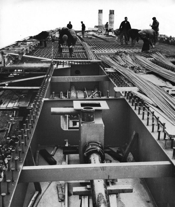
MML Deck A was moved out from its point of assembly during a 55 hour rail possession over Christmas 2002. The deck, complete with deck slab and temporary steel launch nose and weighing over 1000t, was launched using 500t and 1000t hydraulic skid shoes. These ran on tracks on concrete ground beams and fabricated steel beams supported on steel columns founded on piled foundations
The self-powered skid shoes drove the deck out over the railway, until one corner of the deck was over its bearing position which then formed the pivot point for the subsequent rotation. Part of the nosing girder first had to be removed to prevent collision with an existing industrial building, before the rotation could start. For this stage more 1000t skid shoes were used, this time moving along tracks on the bearing shelf, with strand jacks attached to the deck’s main girders pulling on the skid shoes to provide the rotating movement.
Finally, the deck load was transferred to climbing jacks and progressively jacked down with structural bearings attached to the undersides of the beams along the way before the bridge reached its final level and was locked off to allow the bearings to be grouted.