SSDA Awards
SSDA 2002: The Falkirk Wheel
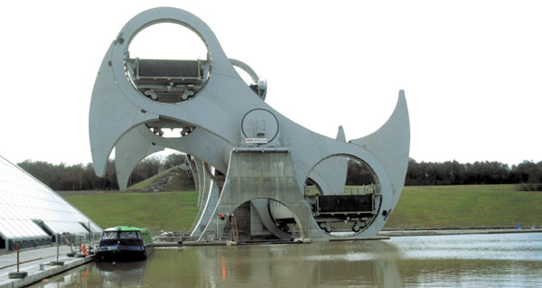
By any measure the Falkirk Wheel is an unusual structure. Weighing approximately 1400t without water it is a large machine. Raising and lowering boats in a rotary motion makes it unique.
FACT FILE: The Falkirk Wheel
Engineers: Arup Scotland, M G Bennett & Associates, Butterley, Tony Gee and Partners
Steelwork Contractor: Butterley
Main Contractor: Morrison Bachy Soletanche Joint Venture
Client: British Waterways
Being so unusual there was no prior experience on which to build the design. As part of a modern leisure facility it was essential that the architectural image be faithfully maintained. As a consequence it was essential that the concepts for the mechanical and structural solutions were developed alongside the architectural image.
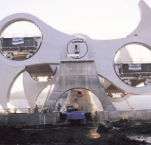
The wheel concept developed is of two arms fixed to an axle. The end of each arm forms a ring within which two gondolas rotate. The very fact that the main structure is a continuous rotating machine means that the principal stresses within the majority of the rotating structure fully reverse each cycle of the wheel. Additionally as the gondolas are supported on four wheels within each arm ring then the rolling loads generate four load stress cycles on the gondola rail support structure every revolution. These fatigue limitations dominated the arms and axle structural design.
To accommodate these high fatigue cycles a combination of bolted and welded construction was adopted. This allowed the ring beam supporting the gondola rail to be a compact construction with the beam diaphragms bolted to the flanges and only welded at the mid third of the beam webs. This cyclic loading and relative flexibility of the ring beams meant that the connection of the beaks, an architectural feature, to the arms would have to either form an integral structure or be so contrived as to not add to the stiffness of the arm ring beams.
The latter option was adopted and the beaks are effectively hung from their centres, with flexible connections at their ends capable of taking the out-of-plane wind loads.The axles presented a particular challenge. The ideal was to fabricate as a single unit. This did not allow trial erection into the arms. To accommodate this and maintain the smooth architectural lines bolted flange joints were included approximately 1m from the arms with the flanges inside the tube of the axle. The fatigue considerations entailed these being constructed using forged rings fabricated into the tube ends with high tensile pre-loaded bolts to form a fatigue resistant joint.
The arms are constructed in sections for HSFG bolt connection on site. The joints were arranged to not only accommodate transport difficulties but to add to, rather than detract from the architectural effect. In all the joints used some 14000 bolts.
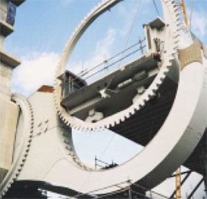
The gondolas are a constantly loaded structure. Had they been static structures there would have been no need for torsional stiffness between the ends. They are, however, rolling within a circular rail and to ensure they remain horizontal at all times they have a timing gear mechanism driven from a static gear on the aqueduct tower. To transmit the rolling forces along the shallow open trough gondola with insignificant torsional flexure required the side beams to be of box construction.
Due to the forces generated within the wheel and resulting deflections it was essential the structure was sympathetic to the loading of the mechanical equipment and likewise the mechanical equipment was designed to be sympathetic to the structure.
This entailed not only producing finite element models for the wheel structure but also separate models for the gondola ends and the main shaft flange bolting. The models were used in particular to predict the loadings on the rolling elements of the main bearings, the alignment of the main drive gears and the fluctuating loads within the main bearing bolts.
As stated earlier there is no specific prior art on which to base the wheel design. While, in general, design for wind loading is well known, the nature of the wheel design led to possible interactions within the structure. Wind tunnel tests were therefore undertaken to confirm the dynamic response of the structure.
Only by employing these detailed techniques was it possible to produce an efficient design realising the architectural aspirations developed in the initial concepts.
The structure including the gondolas was designed to eliminate all site welding and facilitate the full works trial erection of critical elements.
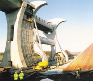
The wheel was delivered to site by road in some 40 major components. The longest element was approximately 21 metres, the widest 5 metres, the highest 5 metres and the heaviest approximately 80 tonnes.
The individual elements were pre-assembled at low level into a series of major lifts. The main erection was carried out in a five-day period using a Demag TC3300 (1000t capacity) strut jib crane.
The maximum single lift was 270 tonnes. The gondolas (complete with bogies and gearing) weighed approximately 180 tonnes and were both erected on the same day.
The main erection was completed in September 2001, and the fitting of ancillary steelwork, gates and other components were completed in time for the first turn of the wheel in early December.
Judges’ Comments:
Reminiscent of the engineering feats of the past, this project has produced an innovative and unusual structure. Its apparent simplicity belies the complex engineering and fabrication solutions that have been devised and used to both construct and operate safely, this eye catching, large machine. In its setting, it will be a long lasting demonstration of engineering in steel.


