Projects and Features
Short Span Railway Underbridges: Developments

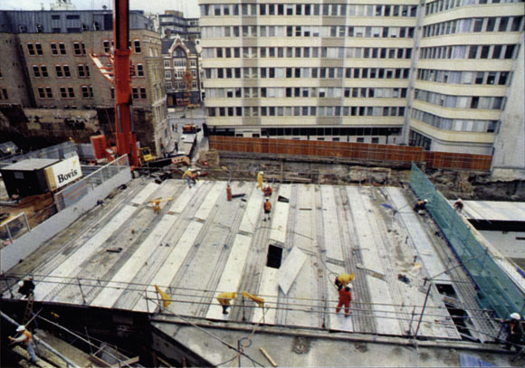
U-deck at Templecombe in Somerset
U-deck railway underbridges have been developed to accommodate the latest requirements, and many have recently been installed. Neil Sadler and Tony Wilkins investigate.
New Civil Engineer magazine reported in April 1997 on the introduction of Cass Hayward’s U-deck design for short to medium span railway underbridges. Each half-through trough shaped structure was to carry a single track on ballast and two versions of the design had been developed as alternatives to the Ztype design established by British Rail and modernised by Railtrack. A pair of all-steel Udecks had been used to replace a life-expired twin track structure at Dunton Green Station in Kent and, shortly after, composite U-decks were used for a twin track reconstruction on the Settle-Carlisle route at Appleby. The principal merits of the new designs were:
- Total off-site manufacture – leading to rapid installation by crane
- Minimum possible new construction depth – demanded by low headroom (bridge bashing) locations to avoid track lift or road lowering
- Strut capacity – to restrain existing abutments where necessary
- More rigid floor diaphragm less susceptible to damage from “bridge bashing”
Since 1997 Cass Hayward U-decks have proved popular with railway authorities and contractors leading to the increased experience and design developments which are described below. Reference is also made to Mott MacDonald’s U-decks developed specifically for high-speed sites.
Completed bridges
Nine underbridge reconstructions using Udecks have now been completed to Cass Hayward designs and final drawings are ready for a similar additional number of replacement bridges planned on the rail network. To date the span range has been from 7.3m to 14.5m. The design has proved economic for spans as low as 7.3m for the two decks replaced within a multi-track road crossing near Salisbury station. The longest span completed remains at 14.5m for the Appleby structure and skews up to 38° have been accommodated. The new bridges are located throughout the UK from Templecombe in Somerset to Dalnaspidal in the Scottish Highlands, and each site has brought its own particular demands leading to a number of variations and developments of the 1997 designs.
Design development
The original all-steel design has not been repeated largely due to economy, slimmer construction and preference for the smooth external appearance offered by the design with the composite floor. To achieve compliance with current railway design standards, more recent U-decks have featured a deeper girder adjacent to the track recess to provide a robust kerb to contain the wheels of derailed vehicles (fig 1).

Figure 1: Cass Hayward U-Deck variations
With the benefit of feedback from the early installations, bearing design has been modified to provide increased tolerance for site assembly during track possessions. Bearings are purpose-designed fabricated steel rockers with separate hold down devices to resist uplift and consequent track movements under vehicular collision impacts from the road below. The risk of “bridge bashing” is a primary concern and during initial design stages generates the demand for minimal construction depth below the ballast to maximise headroom below. At a number of the sites collision beams have been provided to arrest errant vehicles before damage to the main bridge deck can occur.
Usually the collision beams are designed to have a dual function in providing a track maintenance walkway that would otherwise be supported by brackets cantilevered from the main structure. Concrete-filled steel trough girders were utilised for the collision beams at Templecombe whereas precast concrete beams were used at Beattock in Scotland. The collision beams are normally supported on ‘extensions’ of the new precast concrete cill units that are provided to accommodate bearing fixings and distribute loads to the retained abutments. At a new U-deck bridge over Kent Road in Southampton tubular steel collision beams were connected to the abutments independently of the elements of the new superstructure.
Structural form
The principal structural form of the U-deck has largely remained unchanged with composite action between the steel soffit plate and the reinforced concrete floor slab mobilised by mechanical interfaces including shear studs. Variations have occurred predominantly with edge details. All elements have to be detailed carefully to ensure fit to the existing structure footprint and, in addition, the edge details have to accommodate trackside services for signalling and telecommunications. At the Waterworks Tip site in Wakefield collision beams were not required, but precast concrete units were used to provide the edge walkway and services support over the span as an economic alternative to the more standard cantilevered steel arrangement. Trial erection of U-deck and abutment cills to confirm fit prior to railway possession has been commonly adopted and for many of the projects it has proved convenient for the concrete elements to be cast at the steelwork contractor’s premises so that dimensional controls are readily achieved.
Locations
Cass Hayward U-decks have been constructed on primary routes including the Beattock bridge on the West Coast Main Line and at Little Heck on the East Coast Main Line near Selby. A series of U-decks developed by Mott MacDonald are being constructed elsewhere on the West Coast Main Line as part of the high speed line route modernisation project. A detailed assessment of existing bridge stock for potential dynamic problems identified a number of superstructures where high-speed traffic may lead to excessive deck excitation with associated risk of ballast instability. Intricate and costly stiffening work was deemed not feasible for five such superstructures and replacement with a novel U-deck developed by Mott MacDonald was the client’s preferred option.

Figure 2: Mott MacDonald’s U-Type for high speed operations

High speed U-deck at Polesworth during construction
The replacement structures, in common with the earlier U-deck design, have minimal construction depths and to comply with the stringent dynamic performance criteria imposed for running speeds above 125mph, relatively high mass and stiffness is required. For these reasons Mott MacDonald developed a superstructure formed of thick plates comprising a 150mm thick steel deck slab, top flanges up to 200mm thick and thick web plates that require minimal stiffening. A typical cross section is shown in Fig. 2.
This configuration provides the overall stiffness required to avoid excessive dynamic effects, optimises construction depths and does not require a reduction in ballast depth or headroom.
The plate thicknesses exceed those commonly used in short to medium span UK bridge construction so material specifications and welding procedures and details were developed alongside the detailed design. Particular attention was paid to the provision of suitable load paths through connections with a view to achieving the security offered by the original U-Deck and traditional designs.
To date, spans from 7m to 12m and angles of skew up to 45° have been detailed and it has been possible to provide the required minimum 300mm ballast with construction depths as little as 850mm. The simplicity of the design has minimised fabrication time and the philosophy behind the U-type structures has been upheld by providing a low construction depth, robust structure that takes full advantage of maximising prefabrication.
Opportunities
Programmed investment in structural renewals by Network Rail is likely to create opportunities for further development of Udeck underbridge design, some of which have already arisen but not yet come to fruition. Scheme studies of span extensions beyond 20m have been proved viable by widening of the trough and increasing edge girder depth. U-decks with inclined webs have been proposed to achieve improved clearance to the kinematic envelope and to refine the appearance of longer bridges. Multiple span structures are being investigated in continuous and simply supported arrangements. Structural depth limitations at some sites have proved to be extreme leading to consideration of tracks fixed directly to the composite concrete or structural steel floor slab.
The steel slab floor also offers an ultraslim deck on lines where speeds do not exceed 125mph and ballasted track is preferred with a construction depth less than 800mm then achievable. These are just some examples of ways in which the U-deck principle can be extended to produce a wider range of improved bridges for the next generation of railways and the authors would be pleased to hear of the experience of others with these types of bridges.
Further reference to the U-Deck and other designs will be available in the forthcoming SCI publication P318, Design Guide for Steel Railway Bridges. Neil Sadler is a Partner in Cass Hayward & Partners. Tony Wilkins is an Associate Engineer in Mott MacDonald.