Projects and Features
Shaldon Bridge Strengthening


Shaldon Bridge is a concrete viaduct, with a lifting span, across the River Teign and adjacent marshes. It has been strengthened with steel. Work was complicated by the fragile environment, the need to keep the bridge open, and working when the tide allowed. Andy Matthews and Peter Davies report.
FACT FILE: Shaldon Bridge, South Devon
Designers: Engineering Design Group Devon County Council
Main contractor: South West Highways
The existing Shaldon Bridge is a 324 m multispan structure over the Teign Estuary between Teignmouth and Shaldon in South Devon. The bridge was subjected to a weight restriction of 7½ tonnes, which the strengthening works sought to remove, whilst minimising traffic disruption to bridge users and enhancing access for pedestrians and cyclists.
History
In 1824 the Teignmouth and Shaldon Bridge Company was established to raise money to build a toll bridge across the River Teign. The bridge was designed by Roger Hopkins of Plymouth and was opened on the 8th June 1827.
In 1926 an Act of Parliament was passed to widen and strengthen the bridge due to increasing traffic. The new bridge was constructed between 1930 and 1931 with 23 spans varying in length from 9m to 18m. It consisted of four concrete encased steel girders spanning between piled concrete piers and supporting a reinforced concrete deck. At the northern end of the fixed spans a lifting span was constructed consisting of four steel plate girders supporting a timber deck. The carriageway and narrow footways at either end of the bridge are supported on masonry causeways and abutments with masonry parapets. (Fig 1).
In 1990/91 the bridge was assessed as part of Devon’s Assessment and Strengthening Programme and as a result a 7½ tonne weight restriction was imposed as the footway cantilevers and the bridge’s lifting span timber deck were found to be inadequate. Subsequently, in April 2000 a budget of £3,100,000 was made available to fund a strengthening scheme for the bridge designed by the Engineering Design Group of Devon County Council.
Design of the Strengthening Works
The principle considerations governing the design of the strengthening scheme for the main bridge were traffic, tidal working, and loading on the existing foundations, and these controlling factors restricted the choice of potential strengthening solutions.
A conventional overslab solution was initially considered. This involved casting a complete new deck slab with footway cantilevers on top of the existing structure. However this design was rejected, mainly for two reasons. Firstly it could only be constructed under permanent single-way traffic flow resulting in excessive congestion, and secondly the existing bridge foundations would have to be reinforced to cope with the extra dead load imposed.
The preferred scheme involved the construction of an independently supported structure that could be constructed along one side of the bridge at a time, and still enable two-way traffic to be maintained for the majority of the time. Short periods of intermittent single-way flow using stop/go boards or traffic signals were only required during the installation of the temporary traffic barrier, demolition over the deep water channel, piling and concreting works. The pedestrian route was maintained by diverting it at either approach causeway onto the opposite footpath from the works.
Consideration was also given to river traffic. The River Teign is popular with both fishermen and leisure craft, and it was therefore essential that the new structure did not encroach on the waterway or reduce headroom. The new span arrangement was chosen to match the existing bridge spans and would be supported on piles founded on the bedrock some 20 m below beach level.
Traffic Considerations
The bridge forms a vital link within the principal road network for the area. Traffic and pedestrian flows are generally high during peak hours throughout the year, and especially so during the holiday periods. For this reason single way working was only permitted outside the summer holidays for short periods.
Tide Considerations


Spans 6 to 23 are over the Salty, which dries out during low tide for approximately four hours. Conventional reinforced concrete piles and pile cap construction was considered but rejected because of the limited low-tide period for fixing steel and pouring concrete.
The design had also to consider the environmental aspect on the surrounding shellfish beds around the area of the bridge, which had to be protected from contamination.
Finally, the design of the strengthening works would necessitate driving new piles close to the existing bridge foundations. The existing piles are driven six metres into a loose to medium dense gravel layer that overlies weaker silts and silty clays. It was proposed to drive the new piles either into this gravel layer or up to 20 m to reach the bedrock (Breccia) that underlies the site.
It was vital to check that this operation could be carried out without disturbance to the existing structure so in 1999 a test pile was driven in advance of the main contract, whilst carefully monitoring the adjacent structure to ensure that no disturbance took place. The test pile was installed successfully and eventually incorporated into the permanent works.
The Main Bridge Strengthening
It was finally decided to strengthen the 23 fixed spans by removing the existing concrete edge slab and parapets and driving new tubular steel piles to support wider combined footways and cycleways with new parapets. (See figure 2 for a cross section of the original and widened bridge). The new superstructure construction is a reinforced concrete slab composite with steel plate girders supported on tubular steel columns that are a continuation of the new piles. The new slabs are tied together beneath the existing bridge deck slab by 32 mm diameter stainless steel Mac-alloy bars. It is an advantage for the new slabs to be wider than the original footways as they are “balanced” on the new plate girders and therefore impose no extra dead load on the existing structure.

Steel driven piles were chosen to support the new structure. Most of these could be installed between tides, and piles within the deep-water channel could be installed from a crane mounted on a barge. The piles were driven using both a vibrating and impact hammer. Line pipe sections were chosen for the piles (508 diam. 21 mm thick), and these were driven through the beach material and finally to a set of 10 blows per 30 mm, which corresponded to a “CAPWAP” (see Note) calculated capacity of typically 350 tonnes. With the piles in place the steel columns could then be positioned on top of them, which in turn support the new steel beams.
An alignment tube with a load transfer plate was originally designed to provide site tolerance for piling. In consultation with the South West Highways Ltd (the main contractor), the design was modified to avoid the on-site welding of the plate. The altered design transferred the load via the steel cone (analogous to a post-tensioned anchorage). The main beams were designed to support all the falsework, formwork and access platforms required for the construction of the new footway slab. The main advantage in designing the steel beam to support the temporary working platform is that the concreting works would not be tidally dominated and construction could progress at any state of tide. In order to provide a “clean” elevation the plate girders were a constant depth of 1m for each span, the flange thickness varying from 15mm to 25mm depending on the span.
The lifting span timber deck for both the lifting and falling spans of the structure needed replacing. The lifting section of new deck is a lightweight construction in the form of an orthotropic steel deck, and the falling span was designed in reinforced concrete to improve the balance of the structure. The new steel deck was designed to accommodate the wider combined footways, cycleways and new parapets.
Investigations and detail design (commenced in August 2000) by the Engineering Design Group at Devon County Council. The contract was put out to tender in January 2001 and was awarded to South West Highways Ltd. Works began in late March 2001 and were completed, on programme, in November 2002.
The project form of contract was the Institution of Civil Engineers 5th Edition with a post tender Partnership agreement.
Construction of the Strengthening Works

Due to the nature of the environment, the contractor had to maximise their efficiency by carefully planning their operations around the tides.
The demolition, the piling, the erection of the column alignment tubes and the erection / dismantling of the falsework over the Salty was primarily undertaken at low tide.
In the channel the demolition and the erection/dismantling of the falsework was undertaken at high tide using barges moored to the existing piers to provide a safe place of work. The piling and the erection of the column alignment tubes were undertaken at low tide using a crane mounted on a barge. During all demolition and piling operations stop/go traffic management was used in order to provide a safe working zone.
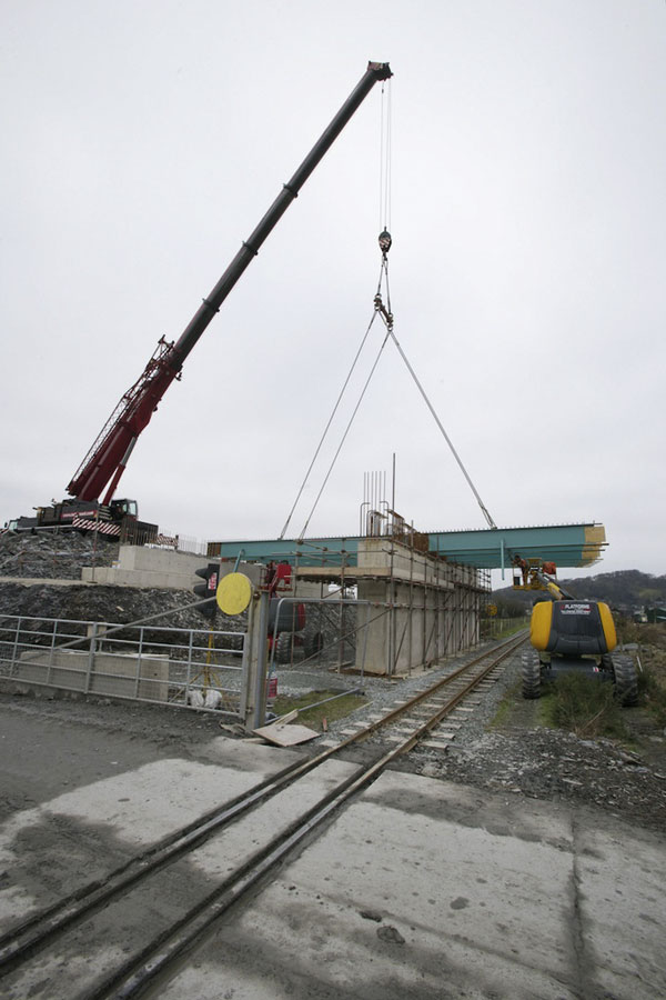
The steelwork over the Salty was erected using a crane on the beach at low tide whilst the beams over the channel were erected from the existing carriageway using a mobile crane unit during over-night closures. The beams were designed with halving joints in order to accommodate sliding bearings and fixed to the columns using high strength friction grip bolts. With the falsework system supported off the new steel beams in place, the formwork and the fixing of the steel reinforcement could commence without effecting the bridge users. Deliveries and concrete pours were undertaken using stop/go traffic management outside peak times to minimise traffic disruption.
The most complex element of the scheme involved renovating the 1930s lifting span and rebuilding the Teignmouth Causeway. The contract stated that a single lane of traffic flow must be maintained at all times during the renovation process. Therefore the new steel trough deck had to be fabricated and erected in two halves. This was managed on site by diverting the pedestrians onto a scaffold walkway to the east of the existing structure.
The vehicles were then diverted onto the old footpath, which in turn provided enough room for the construction works. The original timber decking was removed and the original beams were cleaned and painted with a maintenance paint system, the top coat colour matching the new beams. The new deck was lifted in place during two separate night closures and bolted together and to the original beams using high strength friction grip bolts. The concrete to the causeway walls was placed by pump and in order to achieve the same appearance as the old causeway the original masonry was cut and used to reface the new structural walls.
The scheme was delivered to quality, on time and to budget with minimal disruption to the general public. This success was built on the close relationship between the designer, the contractor and the general public. Both Devon County Council and South West Highways regularly attended local council and commerce meetings to give presentations on the scheme in addition to a bi-monthly newsletter which was produced to inform the general public of the progress, items of interest and forthcoming programme.
The Future
There is a clear public perception that the widened footways on the strengthened bridge should be continued along the adjacent causeways. This coincides with a study to provide a National Cycleway Link from Newton Abbot to Teignmouth on the North side of the Estuary, including a link from Shaldon. A recent Public Consultation on this was favourably received and it is hoped to construct it in the near future.
Andy Matthews is Professional Engineer (Bridges) at Devon County Council and Peter Davies is Contract Manager at South Western Highways.
Note: “CAPWAP” is a monitoring system that calculates the pile capacity during driving using strain gauges, accelerometers and a computer soil/structure interaction model. Ref. Steel Bearing Piles Guide by the Steel Construction Institute.