Projects and Features
Reconstruction of a 1920’s Steel-Framed Office Building

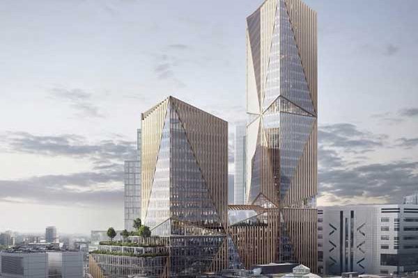
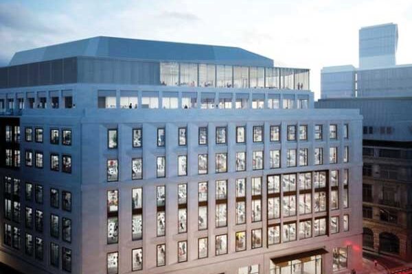
Fig. 1. Main elevation
An example of the difficult problems that can be faced in this type of work: constricted location, adjacent listed buildings, elaborate temporary works, three party walls, facade rebuilds, transfer structures, interfaces with existing work, and location over a railway tunnel. 400 tonnes of existing steelwork was retained.
68 King William Street, London EC4TEAM
Client Synaten
Architect Elsworth Sykes
Structural engineer Peter Brett Associates
Main contractor Try Construction
.
COST AND PROGRAMME
Floor value (new) £1,760m² (per typical upper floor)
Steelwork tonnage 490 tonnes (new)
.
TECHNICAL
Design code BS 5950
Structural analysis package CADS Analysis 3D
Detailing application AutoCAD
Steel grades used BS EN 10210 S355
Fire Protection specification 2hr site applied cellulosic intumescent coating to new steel 2hr vermiculite spray to existing steel where exposed
68 King William Street was the former Lloyds Bank/Guardian Assurance Company building and typifies urban regeneration projects in the City of London. This particular building posed many of the classic difficulties associated with such projects. It is located at the northern end of London Bridge and sits directly over the Docklands Light Railway tunnel at its junction with Monument tube station (fig. 1). The site is in a conservation area and adjacent to the Grade 1 listed St. Clement’s church designed by Sir Christopher Wren.
The aim of this £20m project was to provide a mixed-use building of five retail floors on the lower levels and five office floors above. The client’s brief required the demolition and rebuilding of the upper floors, using the minimum possible structural depth, and the re-use of the existing structure below fourth floor. The existing façade was retained and a design life of 60 years targeted for all structural elements.
Due to its congested city-centre location, its complexity and sequence of construction, the project generated a wide range of challenges. These included elaborate demolition and temporary works packages, party wall junctions with three other buildings, stone and brick façade rebuilds, transfer structures, complex interfaces between new and existing structures and the opening of a basement connection to the Monument subway tunnel.
ORIGINAL CONSTRUCTION
The original office building was erected in 1920-22, as a concrete-encased steel frame with two basement levels, a mezzanine and eight upper storeys. At roof level the building was crowned by a copper-domed Portland stone cupola 6.5m in diameter and 13.0m high. Each floor plate was approximately 1,000m².
Unusually, the building was constructed by two contractors as two distinct frames, east (Trollope and Coll Ltd.) and west (Higgs and Hill Ltd.) of the building centreline, with shared columns along the centreline of the building and with shared facades front and rear.
Clay pot and concrete rib floor slabs were used in the eastern half; the western half was steel filler joists and concrete-infilled triangular clay pot slabs. Steel beams and columns were generally single or double UB sections with plating riveted to the flanges. These had been shop riveted, brought to site and in the case of columns, spliced with on-site riveting instead of bolting. End connections were typically bearing angle cleats top and bottom.
The front façade was constructed in Portland stone with brick backing, the rear façade in glazed brickwork, the thickness decreasing with the height of the building. Both the stone and brick facades were selfsupporting and monolithic around beams and slabs. Slip bricks were used in some locations with unprotected steel some 30-40 mm from the external face of the brick façade. These areas showed the most damage due to corrosion of the steelwork. These monolithic facades together with internal masonry shear walls provided stability for the building.
The foundations were concrete-encased steel grillage pads for the western frame and steel grillages founded on a mass concrete raft approximately 1.7m deep for the eastern half, there was no sign of differential movement damage to the shared façades.
SITE INVESTIGATION
A programme of site investigations included the following items:
- radar testing to locate existing foundation pads,
- ground investigation included seven trial pits and three boreholes,
- soils analysis to enable precise foundation heave calculations,
- metallurgical and tensile tests of existing steel. Coupons were taken from existing beams, columns and samples taken of concrete reinforcement.
- intrusive investigation of around 60 concreteencased steel elements to investigate existing structure,
- load testing of existing suspended floor slabs,
- a topographical survey of the building,
- compression testing of the original party wall brickwork,
- a condition survey of the Northern Line tube tunnel, in conjunction with monitoring of the building to assess movement of the tube line during demolition and rebuild.
A search for historical information was done in conjunction with these investigations and yielded the original construction plans and details for the eastern half constructed by Trollope and Coll. These were found to be accurate and beneficial for designing junctions between the new and the existing structure.
The existing steelwork had an average yield strength of 285 N/mm², equivalent to a grade 40 – 43 steel. The average carbon content was 0.2%, but this varied from 0.06 – 0.35 per cent and care was taken to examine new welds to existing steel for any signs of cracking. The round reinforcement bars had an average yield strength of 372 N/mm².
The ground conditions were found to consist of 2m of made ground over 3m to 5m of medium dense Taplow Gravels over very stiff London Clay to depth. The water table was approximately level with the underside of basement floor at 7m below ground.
Calculations were undertaken to assess the heave on the underground tunnels resulting from demolition and reconstruction of the building above. It was shown that the vertical stress change on the tunnel lining was around 21 kN/m², which was around 4% of the existing 560 kN/m² total stress, a figure deemed acceptable by LUL.
SITE CONSTRAINTS
These were:
- Party walls to east, to roof level, and to the sixth floor on the west and north with shared (party) lightwells.
- No vehicular access to the rear of the building and to the front restricted.
- Limited crane support and oversailing issues.
- The DLR tunnel directly under the building and the Northern Line tunnel about 20m underneath the adjacent King William Street.
APPRAISAL OF THE EXISTING STRUCTURE
It was apparent that the existing slabs to be retained at Level 4 and below would need to resist slightly higher loads than the original “design” values. However the existing columns would have reduced loads due to the new lighter Slimflor construction on upper levels.
At the time of the original design, the London Building Act (1909) required the floors of “counting houses” to be designed for an imposed load of 100 lbs/ft² (4.8 kN/m²). To account for the extra loading from a (4+1) kN/m² imposed load and tenant finishes (1.75 kN/m²), the retained floor slabs were justified by back analysis and subsequently load tested to demonstrate a margin of safety. The inherent redundancy of the existing beam and pot slabs was proved and estimated to be up to five times the required capacity.
An analysis was then carried out for the beam and supporting riveted angle cleat connections. Back analysis was initially carried out using rivet strengths and steel stresses from the BCSA historical structural steelwork handbook. The compound columns were also assessed in this way, conservative limitations being placed on allowable stresses. Capacity was then assessed which used the steel grade indicated by tests and the SCI Appraisal of Existing Iron & Steel Structures recommendations for material factors, etc. Columns were finally design checked to BS 449 using 165 N/mm² strength as had been indicated by the material test.

Fig 2
Some defects were apparent in the existing steel sections, namely the presence of what appeared to be hairline cracks, caused by segregation of impurities formed during rolling. One case is shown in Figure 2. Strengthening details were designed to bridge across such defects.
In summary, when new loads exceeded original “design” loads a combination of “second stage assessment” plus material and load tests was done. Column loads were reduced due to the lighter new construction on floors 5 up to roof level.
DESIGN DEVELOPMENT
The upper five floors and cupola were demolished and rebuilt with greater floor heights and on a regularised 6m column grid. This change in column grid required a grillage of transfer beams at 4th fourth floor level.
At feasibility stage, new floor thicknesses were assumed to comprise 150mm o/a raised floor, a 750mm zone for structure and services and a 150mm ceiling lighting zone. The most efficient structural floor system for the building was found to be the Slimflor system, using 203 UC composite beams in the same depth as the PMF 225 deep profile decking and a 305 mm lightweight concrete slab.

Figure 3: Slimfloor Soffit

Fig. 6. Twin long-span beams
This system provides a notionally flat soffit and an overall structural depth of 305mm for ease of services distribution in the 400mm nominal zone provided below the structure (Fig. 3).
In some areas, twin Slimflor beams were used to obtain spans of 11m as in Figure 6. Some of the transfer beams at sixth floor and roof levels were 630mm deep plate girders with web openings. The deep decking spanned up to 5.8m unpropped and the lightweight concrete slab helped to reduce loads on the existing columns, being some 10-20% lighter than the existing slabs.
Connections of new to existing steelwork below fourth floor level replicated the original steel angle cleat connections and column moments were no higher than the original design (Fig. 4). For ease of new beam installation, a detachable stub of equal section size was connected to one end of each beam, bearing onto the newly installed angle cleat (fig. 5). This gave adaptability for steel erection, working in confined and congested surroundings. Stability of the modified building was provided by three new concrete cores.
An interesting aside to the main building was the modification of the brick arches forming the pavement adjacent to the basement catacombs of St. Clement’s Church. Certain arches were removed to transform a stepped walkway into a goods access ramp for the retail tenant. The existing 300mm deep cast iron beams had an unusual asymmetric section, shown in Figure 7.

Fig. 4. Connection of new to existing

Fig. 5. New columns and beam connections

Fig. 7. Original 300mm deep cast iron beams
CRANEAGE AND TEMPORARY WORKS
The congested city centre location of the site meant that only one crane of significant lifting capacity (six tons) could be accommodated. Nearing completion date, a one-ton capacity crane was installed on the strengthened roof slab.
The installation of temporary works to stabilise the retained structure and façade began in June 2001 in tandem with partial demolition. Temporary bracing works, all within the floor plan of the building, used the retained existing frame and foundations where possible.

Fig. 8. Retained facade propped off retained structure
On the western and northern side of the building, the basement extended 4m below the adjacent foundations. Extensive propping was required. Due to the core construction in the same areas, layout of these props was complex and some were cast into core walls as their construction proceeded.
Retention of front and rear facades was also based on propping off retained structure (fig. 8). In core areas this was not feasible, leading to eight storeys of retained façade in places. The three new core areas were required to be demolished down to basement level, giving ten storeys of retained party wall on each side of the building.
FAÇADE RECONSTRUCTION
The existing Portland stone and glazed-brick façades were removed down to the sixth floor and rebuilt to match the higher floor levels with new courses of stone or brickwork inserted at various levels.
Reconstruction of the stone façade was carried out in the same monolithic construction as the original but introducing a blockwork backing structure. This led to complex detailing of DPM’s and insulation details. In order to ensure that the façade remained self-supporting and that no additional load was carried by the existing steel structure, the edge beams and concrete slab were dry packed into the stonework. Gaps were left in the dry packing at one metre intervals to allow for drainage, and insulation installed along the top of the slab and soffit to avoid cold bridging.
The retained areas of existing steel embedded in the stone front façade were in some cases corroded. In accessible areas, stone was removed locally, the steelwork cleaned and coated in bituminous paint and the stonework replaced. Cathodic protection was considered for the inaccessible areas of embedded steel. It was deemed unnecessary, as the amount and rate of corrosion were shown to be small, and the capital cost and maintenance of the CP system high. An inspection and maintenance plan was adopted as part of the future management of the building.
SUMMARY
This project demonstrates the resilience, adaptability and long-term value of a steelwork structure. Approximately 400 tonnes of steelwork was retained in place. In other words, structure with zero cost to the environment. For comparative purposes, a tonne of new steelwork used in a building has about 47 MJ of embodied energy, equivalent to the energy used by a conventional house in a year.
AUTHORS
Dr Fergal Kelly, Principal Engineer; John Rushton and Bob Brickwood, Partners of Peter Brett Associates.