Projects and Features
SCI’s new Software SATEL Delivers Simplicity in Explosion Analysis
Viken Chinien introduces SATEL, a new package that incorporates the latest theoretical developments and extends the applicability of traditional design methods for structures subject to blast loads.
The SCI has developed state-of-the-art software SATEL (Structural Analysis Tool for Explosion Loading) for the analysis of single-degree-of-freedom (SDOF) systems subjected to explosion loads. The software is based on pioneering theoretical developments described in the Fire and Blast Information Group (FABIG) Technical Note 7(1) and provides analysts and designers with the practical means to perform explosion analysis without recourse to complex implicit or explicit non-linear finite element analysis (NLFEA).
SATEL allows designers to account for plasticity, large displacements and strain rate effects in their SDOF analysis of structural members and panels under explosion loading. It can be used in many practical applications where structures can be modelled as SDOF systems, such as blast walls and structural members or panels in buildings, ships and offshore platform decks. It enables designers to quickly assess the structural performance of the system, particularly at the preliminary design stage, leading to a substantial reduction in the costs for such analysis.
The software was developed as part of a Joint Industry Project and incorporates the following features:
- It extends the limit of applicability of the traditional Biggs method(2) to account for unequal support capacities, finite support axial and rotational stiffness and capacity, strain rate effects and improved methods for determining plastic strains.
- It provides a user-friendly interface designed in collaboration with the project partners. This uses familiar interface controls — that is, it looks and feels like standard desktop software using Microsoft Windows controls.
- It is supported by a Theory Manual and a User Guide, which gives background to the calculations and guidance on use of the package.
Theory and Assumptions
Single degree of freedom systems are those in which the response of the structural element or system to an explosion is dominated by the first mode of vibration. It is restricted to structural systems which may realistically be simplified to a single mass on a spring.
The most widely applied SDOF model has so far been that of Biggs(2) which suffers from the following shortcomings:
- It does not incorporate the effects of support flexibility, since it assumes either pinned or fixed conditions.
- It does not account for different moment capacities at the two supports.
- It ignores the catenary effect, which has a significant influence on the large displacement member response in the presence of axial restraint at the supports.
- It ignores the influence of material rate-sensitivity
- It ignores the influence of strain-hardening through assuming elastic perfectly plastic material and cross-sectional responses.
- It does not account for the beam-column effect in load-bearing members that sustain significant compressive axial forces.
The approach developed in FABIG Technical Note 7(1) overcomes the first four shortcomings of the Biggs model.
The problem characteristics and assumptions for the new SDOF model are as follows:
- The member has uniform cross-sectional properties along its length
- The cross-sectional response is elastic perfectly plastic (i.e. no strain hardening)
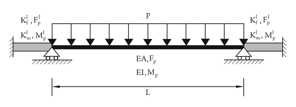
- The member has two end supports where transverse displacements are restrained (Figure 1).
- Arbitrary elastic perfectly plastic conditions are to be considered for the two end supports for both rotational and axial deformations (Figure 1)
- Strain-rate effect is accounted for
- The loading and mass are uniformly distributed along the member length (Figure 1)
- Both bending and catenary actions are to be considered for the member.
Further assumptions were made to facilitate the formulation of a relatively uncomplicated model which should nevertheless capture the essential problem characteristics:
- Static member failure is associated with a three-hinge plastic mechanism for the case of non-zero rotational support stiffnesses (Figure 2).
- The internal plastic hinge is at mid-span.
- The interaction between the plastic bending moment and axial force is linear.
- Material rate sensitivity is governed by the Cowper-Symonds model.
SATEL Development
The software functional requirements for SATEL were developed in conjunction with the partners on this Joint Industry Project (JIP), which included the Health and Safety Executive, defence technology specialist Qinetiq and blast wall manufacturer Mech-Tool Ltd.
The software was designed in a simple and easy-to-use format that guides the user through the various steps by providing ‘hover help’ messages relating to each input parameter. Graphical aids are included throughout to help the user in verifying the input data with warning and error messages, as appropriate, if the validation ranges for the parameters are exceeded.
Development followed the same rationale as other engineering software with input blocks for:
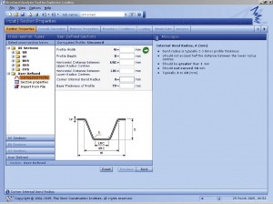
• Section properties (Figure 3)
• Database of UK sections (UB/UC/RHS/SHS/CHS)
• Corrugated profiles
• User defined section properties
• Overall geometry
• Overall length
• Mass per unit length (default value if database section is chosen)
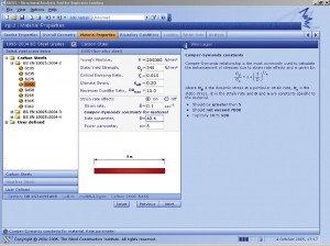
• Material properties (Figure 4)
• Carbon Steel
• Stainless Steel
Users can also define their own material properties. Default values for the material properties are provided for materials in the SATEL database which includes most carbon steel and stainless steel grades. The material properties include Young’s modulus, yield strength, damping ratio, ultimate strain and ductility ratio. If strain rate effects are included, default values are also provided for the strain rate and the Cowper- Symonds constants for the materials in the SATEL database.
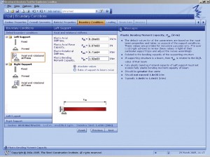
• Boundary conditions (Figure 5)
• Fixed supports
• Pinned supports
• Finite axial & rotational stiffness
• Any variation of the above
• Strain rate
• Reference displacement rate – default value provided
• Support rate parameters – default values provided
• Loading
Three options are provided for the time- history variation of the load, namely:
• Type I profile – triangular blast profile
• Type II profile – triangular blast profile with rebound
• Type III profile – general blast profile
• Analysis
• SATEL analysis screen allows the user to define the duration of the analysis and change the default time-step of 2.0 x 10⁻⁵ seconds
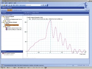
• Output (Figure 6)
SATEL provides the user with three different output screens, namely:
• Summary: provides a summary of the input and output data.
• Results (Figure 6): allows user to plot resistance-displacement curve and time-history curves for all output parameters (left & right support reactions, midspan displacement, velocity and acceleration, mid-span plastic strain, left & right support plastic strain, ductility ratio)
• Calculations Log: provides user with detailed list of all input, intermediate and output parameters used in the calculations including elastic natural frequency, dynamic load factors and rebound dynamic load factors.
The user can export any of the time-history data to text files for further manipulation of data.
A user guide(3) and a theory manual(4) are available online for SATEL.
Availability
SATEL is available under licence from The Steel Construction Institute. For further details and information concerning the software, please contact Dr Viken Chinien (e-mail: v.chinien@steel-sci.com) at the SCI.
Acknowledgements
The development of SATEL was sponsored by the Health & Safety Executive, QinetiQ and Mech-Tool. Their support and help in the project is gratefully acknowledged.
References
(1) Fire and Blast Information Group (FABIG), ‘Simplified Methods for Analysis of Response to Dynamic Loading’, Technical Note 7, The Steel Construction Institute, 2002.
(2) Biggs, J.M., ‘Introduction to Structural Dynamics’, McGraw-Hill, 1964
(3) SCI RP1061, ‘SATEL User Guide’, The Steel Construction Institute, 2005
(4) SCI RP1060, ‘SATEL Theory Manual’, The Steel Construction Institute, 2005.


