Technical
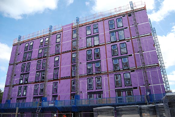
Part L and airtightness of the building envelope

Test facility at Oxford Brookes
Airtightness is likely to become a critical consideration in meeting the new Building Regulations on thermal performance. Graham Raven reports on tests by the SCI and Oxford Brookes University which will help designers and subcontractors devise practical details which perform well.
Extensive changes to the Approved Documents for Part L of the Building Regulations, The Conservation of Fuel & Power were expected to be published in July 2005 for implementation on 4 January 2006. Following a delay in publication the Apoproved Documents were released last month with headline requirements broadly as expected: a 20% reduction in carbon emissions for domestic buildings and 23–28% for non-domestic buildings when compared with equivalent buildings that would have complied with the 2002 Regulations (see news click here). Apart from the need to reduce carbon dioxide emissions a further major change is the requirement to use a national whole building calculation model in determining compliance. Methods based on considering each element of the building individually will no longer be permissible.
The new regulations will be used to implement the EU Energy Performance of Buildings Directive (EPBD) which will enforce energy passports for buildings. The effects of this are already being seen in much greater interest from building owners in obtaining better performance.
For domestic buildings the calculation tool is to be SAP (Standard Assessment Procedure) 2005 which is an updated version of the existing SAP procedures. For non domestic buildings the Simplified Building Energy Model (SBEM) is being developed at BRE. A test version was expected in late September or October 2005.
Methods of Compliance
Although alternative methods have been permitted, much of the industry is accustomed to achieving compliance through elemental methods with maximum U-values being set for various construction elements, a pass/fail limit for airtightness in non domestic buildings and maximum permitted areas of items such as rooflights, windows and doors. In the new regulations, apart from back-stop maximum U‑values (probably the 2002 compliance values) for the various components in the envelope, compliance will only be assessed taking the whole building performance, including services performance, into account. Pre-completion airtightness testing is likely to be required on a sample basis for domestic buildings and all non-domestic buildings above a certain size. This is likely to be set at the existing limit of 1,000 m². There will be a maximum permitted back stop value set at the 2002 compliance level of 10 m3/m2/hr at a pressure of 50 pascals. However as improvements in U-values are reaching the point of dramatically diminishing returns it is very likely that designers will turn to improvements in airtightness as the most economic way of improving the efficiency of the envelope.
For example, in a typical shed building a reduction in tested airtightness from 10 to 5 m³/m²/hr gives an 18% reduction in carbon dioxide emissions while dropping U-values by 0.05 W/m²K from the current compliance levels of 0.35 for walls and 0.25 for roofs gives only around 2% saving. Even this improvement in U-values is achieved by a disproportionate increase in the thickness of insulation in a roof from 160 to 240 mm.
From this it can be seen that there is likely to be a concentration on improving airtightness. There is considerable work to do because although a few companies are achieving good results, demonstrating that it can de done, the general level of enforcement and compliance is currently low. It has been estimated that only one-third of buildings are being tested and of these one-third are failing. Good details with good construction generally give good results, bad details can be rescued by excellent construction and good details ruined by bad construction.
An important feature of the SBEM is that a design value for airtightness is chosen as part of the input; but this value then becomes the pass criterion and has to be achieved in pre-completion testing. This means that there will be a focus on low values for airtightness that are reliably attainable in practice with different types of cladding and in different sizes of building. The smaller the building the more difficult it is to achieve low values.
There will also be a strong focus on whose responsibility it is to choose the design value and whose responsibility it is to achieve it. Pre-completion testing is by its nature at a critical point in the build programme should there be a failure. There may be a tendency to base the design on a low value and then put all the responsibility on the envelope subcontractor to achieve this. A significant problem will be determining where responsibility lies for the interfaces between all the elements: wall, roof, windows, rooflights, doors, smoke vents and any other penetrations which may be formed after the envelope subcontract has been otherwise completed. Developing and understanding the performance of sound details will be of paramount importance. While clearly site performance is critical it will also be sensible to develop data for differing details and how they are affected by sealant positions, flashing configurations, the number and type of fasteners and so on. This will enable designers and contractors to understand achievable levels, good detailing practices and the critical priorities for good quality construction. Clearly there are too many variables on site to develop this knowledge and a practical answer lies in laboratory facilities.
SCI and Oxford Brookes University
In order to offer services to the envelope suppliers and specialist subcontractors the SCI and The Oxford Institute for Sustainable Development (OISD) at Oxford Brookes University are collaborating. A test box (see photograph), has been constructed and is currently being used to assess air leakage rates through the joints of a variety of commercial cladding products, for both built up systems and composite panel.

Sample graph of rig pressure and leakage against time
The objective of this testing is to be able to show for a specific building design that the sum of expected leakage from all the cladding joints does not compromise the ability of the finished building to meet ADL2 requirements. To do this, linear leakage figures (m³ per metre length of joint per hour) need to be measured for all types of joint.
The test cell has been designed to enable sections of cladding system such as wall panels, corners, roof ridges, gables, and eaves to be mounted on top of a perfectly sealed open top box. Air is then pumped into the box to achieve a predetermined pressure, commonly 50 pascals as this is the prescribed test pressure for buildings, and the resulting airflow rate measured to indicate leakage. Leakage rates can be assessed for a range of pressures to give a leakage characteristic for the cladding details under test. Typical results are shown in the graph.
The main output of interest to cladding manufacturers and building designers is the leakage rate of a particular joint per linear metre at the stated pressure differential. Knowing this parameter for all types of cladding joint used in a particular building enables the overall theoretical leakage rate due to joints to be calculated. This is a useful tool to determine the leakage contribution of cladding jointing in a full size building in relation to Part L standards. Clearly the details have to be dependably replicated on site.
Initial test work for Corus Colors has proved the performance and usefulness of the equipment in assessing the effect of different fixing details. The service is now available through SCI to other suppliers and specifiers of envelope systems.
Final Thoughts
Apart from developing a better and quantified understanding of the key issues in cladding detailing for cladding suppliers, knowledge of how details should perform will help in the determination of responsibilities in achieving the required performance of the finished buildings.
A detail that performs well under test, assuming buildability has been taken into account, is capable of performing well when constructed; if it does not it is likely to be because of a workmanship problems rather than design. The facility will also help in developing new details which should be less reliant on site performance.
Graham Raven is the Senior Manager for Construction Technology at the Steel Construction Institute g.raven@steel-sci.com