Projects and Features
Oldham Gallery: Steelwork

Fig 1: External view showing the link bridge between the new and the old galleries (Photo: Peter MacKinven)
Oldham Gallery is a new state-of-the-art gallery facility, and winner of a 2002 RIBA award, on the outskirts of Oldham town centre. Deb Thomas reports.
FACT FILE: Oldham Gallery: Steelwork
Architect: Pringle Richards Sharratt
Structural and Services Engineers: Arup
The Gallery forms the first phase of a new Cultural Quarter to include a new library, adult education centre, museum and performing arts centre. The brief called for a building that would generate a presence of its own and establish a strong sense of place. But being a local authority funded project the budget was limited and largely fixed. A significant portion of this budget was spent on removal of contaminated material from the site, a former gas works. So the design of the building had to be as economic as possible while still providing a sense of grandeur.
The distinctive three-storey gallery building dominates the skyline as the woollen mills and chimneys did in yesteryear. It is 10m wide and 85m long on plan and is divided into three zones along its length. In the centre, there is a double storey height reception space forming a gateway to the new Cultural Quarter. This is flanked by a multi-media education space and a café at ground floor. At first floor level there is a Fine Arts Store, to Museum and Galleries Commission standards, and staff offices.
The galleries themselves are located at second floor level with Museum and Gallery standard spaces at each end of the floor. These are enclosed boxes with a narrow slot at roof level to let in diffused daylight. The central exhibition space, located directly over the entrance foyer, has glazed external walls allowing views out to the nearby Pennines.
The floor levels in the new gallery are set to match those in the adjacent Victorian library and art gallery. A footbridge at second floor level connects the old and the new facilities. The building, up to and including the second floor slab, has a reinforced concrete frame. The floor of the central exhibition space is constructed from long span plate girders acting compositely with a concrete slab on profiled metal deck. The roof of the gallery has a curved steel structure, giving the building its distinctive profile.
This article describes the three main steelwork elements in more detail: the bridge floor at second floor level, the roof structure and the link footbridge. Fig. 1 shows an external view of the building with the link bridge between the new and existing galleries.
Steel Structure
At scheme design stage, the bridge structure was required to span 18.0m between two concrete core walls located centrally within the width of the building and concrete columns at the perimeter. The edge beams of the bridge structure act as transfer beams to support the roof structure over the central exhibition space. With the relatively long floor span, vibration was felt to be a major design parameter.
The client and the architect were happy to read the structural form of the bridge in the finished building but were reluctant to see exposed diagonal bracing. A pair of Vierendeel trusses were proposed at the edges of the floor plate spanning between the concrete columns at each corner of the deck. The bottom chord of the Vierendeel, located at floor level, supported simple steel floor beams spanning across the width of the building.
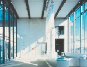
Fig 2: Internal view of the double height entrance foyer with the exposed beam soffits (Photo: Edmund Sumner)
These beams were designed to act compositely with a concrete floor slab. The top chord of the Vierendeel, located at roof level, supported the curved steel roof beams and the outer steel hoops.
A value engineering exercise at detailed design stage necessitated a review of the proposed structural form of the bridge slab. A series of parametric studies were carried out which considered a number of structural options in terms of steel weight and vibration performance. These studies suggested that a series of fabricated plate girders at 2.5m centres spanning, the now reduced, 17.1m between the concrete structure would be the most efficient.
The edge beams, which also support the loads from the roof over the central exhibition space, are 950mm deep non-composite fabricated plate girders. The slab sits within the depth of the beam so that the underside of the beam aligns with the underside of the internal beams. Vertical stiffeners and back span beams are provided at 1.9m centres along the length of these beams to resist the lateral restraint forces from the double storey height mullions supporting the glass wall below. The internal beams are 600mm deep, nonsymmetrical plate girders designed to act compositely with the 200mm deep concrete slab on profiled metal deck. Cross beams were provided at 5.7m centres to help distribute loads from heavy items such as sculpture between the main floor beams. Normal weight concrete was chosen to increase the dead load of the slab to minimise vibrations.
Fabricated plates were cast into the concrete columns and shear walls to facilitate the fixing of the plate girders. The plates had a combination of shear studs and high yield reinforcing bar welded to the back of them to ensure the forces were transferred into the concrete structure. Fin plates were on-site welded to the front faces of the cast-in plates allowing a simple bolted connection at each end of the beams.
The layout and details of the second floor bridge structure are shown in Fig. 3. The bottom flanges of the beams are exposed in the entrance foyer, as can be seen in Fig. 2.
Roof Structure
The roof structure is formed from a series of pin-based portal frames located at each gridline along the length of the building. These portal frames are designed for the vertical load condition only, they are too high to be economically designed to withstand wind loads and meet the geometric criteria set by the architect. Lateral loads are resisted by bays of vertical bracing at the core locations and by plan bracing in the roof.
The columns are formed from 254 x 254mm universal column sections. The roof beams are formed from curved fabricated plate girders, the bottom flanges of which are 250mm wide to match the width of the columns. The bottom flanges of the roof beams support bespoke pre-cast concrete panels to form the ceiling of the gallery spaces and help with environmental control.
The longitudinal roof beams are designed with moment connections at their ends to provided torsional restraint to the roof beams. The plate girders themselves have sufficient torsional resistance to span between the longitudinal roof beams.
The external steel hoops are formed from curved structural T-sections. These support a walkway and balustrade along the full length of the building. At each end of the building the walkway is for maintenance access only, in the centre it is open to the public. The bottom ends of the tees are moment fixed to the structure by a four bolt connection to the steel columns at each gridline, through the concrete upstand between the steel columns in the two end galleries and to stubs welded to the top flange of the plate girders in the central gallery.
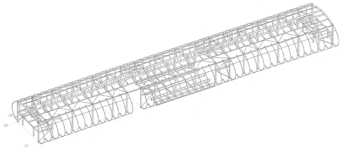
Two circular hollow sections run between the hoops for the full length of the building to tie the hoops together. Four bays of cross bracing are provided to prevent sideways sway of the hoops. A 3-d diagram of the roof structure is shown in Fig. 4.
Link Footbridge
The link footbridge spans across Ashworth Street, now partially pedestrianised, to connect the new galleries to the existing gallery spaces in the original Victorian Art Gallery. The basic structure for the rectilinear bridge consists of a pair of 610mm deep universal beams spanning the approximately 13.0m distance between the two buildings.
These support a series of fixed base portal frames to support the roof and walls. The base moments are transferred into cross beams set within the depth of the universal beams at floor level. A timber deck is supported on timber joists spanning between the steel cross beams.
The bridge sits on four bearings to prevent the transfer of any out of plane forces into the walls of the existing Victorian structure. Of the two bearings on the new structure, one was fixed with respect to horizontal movement, while the other allowed movement perpendicular to the bridge only. Of the two bearings on the existing structure, one was completely free with respect to horizontal movement, while the other only allowed movement parallel to the direction of the bridge.
Several modifications were required to the structure of the existing gallery building to allow the bridge link to be installed. The alignment of the bridge link required the removal of a steel column supporting the mansard roof, an early 20th Century addition to the building. A new transfer beam, installed in two pieces with moment connections either side of the existing column, was thus required to allow the removal of this column. Once the transfer beam was in place, the existing column below the connection was removed.
The bridge beams landed above a pair of brick soldier arches forming lintels to original windows at second floor level. A concrete spreader beam was therefore installed behind the original stone facing to transfer the forces from the new bridge link to the brick piers either side of the windows. Temporary props were installed through the full height of the building while this element of work was carried out.
Deb Thomas is an Associate Director at Arup.


