50 & 20 Years Ago
Nottingham Flyover
 Roads are getting more congested, junctions are becoming bottlenecks – often the only solution is to build a temporary flyover. Mr F. I. Lees, Director and Contracts Manager, The Butterley Engineering Co. Ltd., describes a recently completed structure at Nottingham.
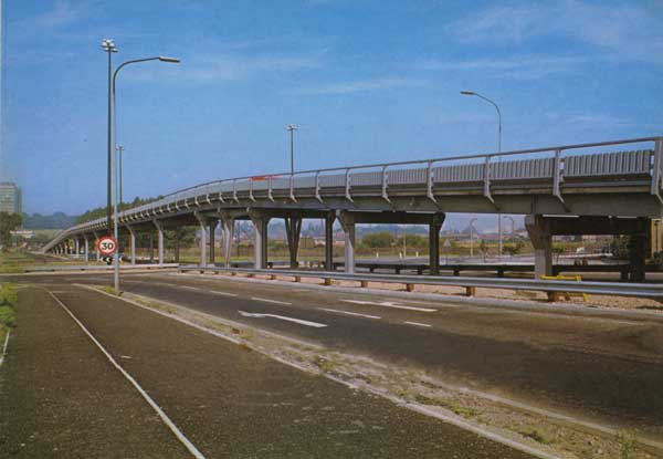
Clifton Boulevard Trunk Ring Road Flyover at Abbey Street Junction was opened to traffic on the 29th July 1969.
The scheme was designed by Mr. F. N. Little, the Nottingham City Engineer, on behalf of the Ministry of Transport, utilising a flyover of the Braithwaite ‘Fliway’ design which was awarded a prize in the competition sponsored by the Ministry of Transport in 1964. Its design is such that it can be dismantled for re-erection elsewhere when traffic conditions on an existing site necessitate works of greater magnitude.
In the present case, the existing roundabout was designed as two levels so that a flyover could be added. The flyover carries Clifton Boulevard (Trunk Outer Ring Road) traffic across the A453 route to Birmingham. By removing the ‘through’ group of traffic from the ground level roundabout its traffic capacity has been increased, and conditions for pedestrians crossing near the junction have also been made safer and more convenient.
Clifton Boulevard has 24ft wide twin carriageways and an 18ft central reservation. Near and alongside the flyover the outer kerb lines are set back to give 23ft. Lighting is by three 80ft high-mast columns carried on foundations at ground level.
To reduce interference with traffic during construction and for convenience on site, a storage and casting yard was established about 600 yards away from the job. During erection, units were transferred from here to the site by mobile crane and low loader. The location of the foundations was governed by the presence of two large sewers beneath the roundabout. It was necessary to use 45ft spans over the roundabout with 36ft spans for both approaches. The flyover has open guardrailing on either side, the running surface being concrete. The portal trestles are protected by ‘Armco’ type crash barriers.
The flyover carries a two lane carriageway designed to take the loadings in the Construction and Use regulations of the Ministry of Transport. It comprises 10 spans of 36ft, 6 spans of 45ft and 4 spans of 18ft. Total spanned length is 702ft plus the approach ramps on solid, giving a total flyover length of 833ft. The width is 25ft 4in overall and between kerbs 22ft. The headroom to the ground level roundabout is 16ft 9in and the gradient is 1 in 15 for the approach spans and 1 in 83 for the centre spans. The foundations are 18in nominal bored piles approximately 25ft long, established in dense sand, with reinforced concrete pile caps and tie beams.
The deck spans of the Braithwaite ‘Fliway’, which are simply supported on portal frame steel trestles, are prefabricated to single traffic lane width and are of steel and concrete construction acting compositely. Each unit comprises two longitudinal universal beams joined by a series of transverse members. Welded studs provide the composite shear connection with the 7in thick reinforced concrete deck slab.
The flyover is anchored to each abutment and also has two intermediate portal braced bays to cater for longitudinal forces. These forces are transmitted through the composite deck units via the cast ‘Meehanite’ bearings, which allow for expansion and rotation movements, and rubber compression pads between the ends of the units, which are pre-compressed during erection.
The parapets are fabricated from rectangular hollow sections and act as crash barriers. The uprights are bolted to the slabs and to the main longitudinal steel beams. Special joints are incorporated in the longitudinals to cater for expansion and to maintain continuity of strength from end-to-end of the ‘Fliway’. PVC coated steel splash panels and flashings are provided.
225 tons of steelwork were used in the superstructure and protection was by grit blasting followed by a four coat paint system. Erection of the deck units was completed in ten days, without interference to traffic at peak period, using a 50 ton capacity lorry-mounted mobile crane.
Two main contracts were placed, one for the foundations and the other for the steel superstructure, approach ramps and decking and other miscellaneous work above foundation level. Two main contractors were GKN Foundations Ltd for the foundations and the Butterley Engineering Co Ltd for the superstructure and associated work. Site investigation was by Le Grand Adsco.
Street lighting was designed by the City Lighting Engineer. Roadworks, direction and other signs were carried out by the City Engineer’s Department. The total cost of all the work, including foundations, superstructure, site investigation and alterations to statutory undertaker’s services, was £160,000. Of this total, the superstructure approach ramps and other miscellaneous work above foundation level came to £79,000 and this cost, divided by the total area of flyover (833ft long by 25ft 4in wide), represents 75/- 0d per sq ft. Similarly the foundations represent a cost of 19/- 0d per sq ft.
Temporary flyovers often provide the only solution to the problems caused by our ever-increasing traffic density. Since the first temporary flyover was built in Birmingham some nine years ago several cities and large towns have found that this type of structure has been the only feasible method of achieving traffic flow without massive reconstruction and high expense. Similar structures have been built for instance at Bristol, Kingston and Barking and in each of these the main framing has been made from steel which lends itself particularly well to the reduction of dead load and simplicity of fabrication both on and off site. It is certain that many more temporary flyovers will be erected in the years ahead and although planned for only a limited life it is reasonable to suppose that many will be giving good service years after their original time span has been reached.
From Building with Steel: November 1969


