Technical
Let the stress cover the strain
For some structures it is necessary to consider elastic behaviour, but for many a designer can adopt more simple plastic design. The latter is particularly attractive for composite construction, not least because you don’t need to get into the sequence of load application, first to steel then to composite components. Graham Couchman of SCI takes a detailed look at the adoption of plastic design for composite beams (i.e. as used in buildings) in light of two recent trends that may add a certain complexity, namely the use of higher-grade steels and the use of deeper slabs.
Either of the two trends mentioned above can mean that in order to achieve sufficient curvature to strain the steel so that it approaches its plastic moment resistance, the strains in the upper fibres of concrete may go beyond the point at which crushing occurs. One way to avoid needing to consider strains explicitly is to limit the plastic moment resistance. According to Eurocode 4 (1) this reduction is achieved through a so-called beta factor, which has been mildly revised, and applied to shallow floor beams for the first time, during the development of the Generation 2 Eurocode 4.
Strain and stress in a composite beam
Designers do not generally worry too much about strain. When designing a composite beam they determine the level of applied moment, and normally choose a section that has adequate resistance using simple stress blocks to determine the forces in the steel and concrete. It is assumed that the materials can strain enough to justify those stresses. When checking deflection the stiffness of the cross-section is determined based on the assumption that strains are sufficiently low that the section remains elastic, and so Young’s Modulus can be used when calculating deflection values. It is generally appreciated that excessive strain could invalidate the stiffness assumptions, and codes sometimes introduce checks to ensure that yielding does not occur at serviceability. However it is also necessary to ensure that strains are not sufficiently high to invalidate the assumptions about stresses that are behind the resistance calculations.
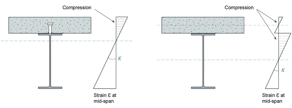
On the assumption that plane sections remain plane as an element bends, as the curvature of a cross-section increases the absolute values of the strains throughout the depth of that cross-section, be they positive or negative, will increase. For those used to considering bending, but not curvature, the former is the curvature multiplied by the flexural rigidity EI. Curvature of a cross-section of a composite beam in which the steel and concrete elements were joined by infinitely stiff (and sufficiently strong) material would result in the strains shown in Figure 1a. A beam of this type would be described as having full interaction. This should not to be confused with full shear connection, which means the sum of the resistances of the connectors is not less than the maximum compressive force the concrete can resist, or the maximum tensile force the steel can resist – whichever is the smaller. Full shear connection is not related to the stiffness of the connectors. Of course nothing in the world of construction is really infinitely stiff – welded headed shear studs will have an initial stiffness of somewhere between 50 kN/mm and 100 kN/mm depending on the slab. A complete lack of stiffness, in other words a non-composite beam, results in slip at the steel to concrete interface, which manifests itself as a step in the strain diagram at that level (Figure 1b). A composite beam with shear connection having a finite level of stiffness would see strains that are somewhere between the two extremes shown in Figure 1. However, things get very complicated when slip is taken into account, so the theory and research reported hereafter ignore it, which is conservative as far as critical strains are concerned.
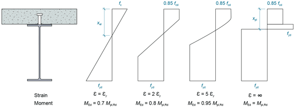
If we now consider the stress distribution in a composite cross-section, the linear distributions of strain in the steel and concrete elements represented in Figure 1a will only be reflected in the stress distributions up to the point at which the bottom fibres of the steel yield. As curvature, and strains, continue to increase the stresses will evolve as shown in Figure 2 for a typical cross-section (with full interaction).
Identifying when curvature becomes a concern
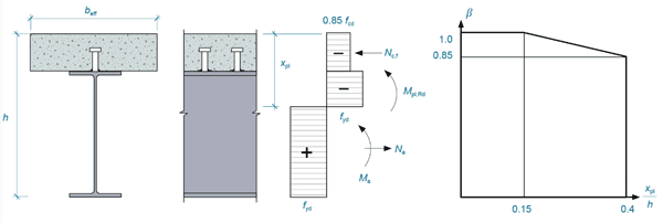
Figure 2 shows that as curvature increases, at a certain point the bottom fibres of steel will start to yield. As curvature increases further this yielding will spread up the steel section, up to the point where a sufficient part of the section is at yield for the part that isn’t, to be assumed to be (yielding over the total depth would require infinite curvature, and as noted above we do not deal with infinite things in reality). It is generally accepted that achieving 0.95Mp in a numerical model, which simplifies the modelling, is sufficient to represent the ultimate capacity of a beam. The work carried out by ourselves in the development of the rules for P405(2) adopted this approach. Further increasing curvature would be no problem for the steel, in fact we may start to see some beneficial strain hardening of the bottom flange, but it may be a problem for the concrete, which will have a crushing strain of say 0.35%. The further the top fibres of concrete are from the neutral axis (so with a deep slab), or the further the curvature has to go in order to fully yield the steel (so exacerbated with higher strength steel), the more likely this is to be a problem. When concrete crushing occurs it will limit the cross-sectional resistance. At some point, which is a function of the steel grade and position of the neutral axis, one can no longer assume plastic stress blocks for both the steel and concrete, for this reason. However, it is possible to use a reduced plastic resistance such that the calculation remains simple. This reduction is achieved using a so-called beta factor.
Reducing the effective plastic moment resistance
Eurocode 4 (EN 1994-1-1 clause 6.2.1.2 (2))(1) provides a graph showing the beta factor that is to be used for composite beams using S420 or S460 steel. This graph is reproduced here as Figure 3.
This phenomenon has been investigated further in recent years as part of the development of the Generation 2 Eurocode 4. Tens of thousands of numerical simulations were used to refine the rules, and extend them to consider shallow floor beams as well as downstand beams(3). To avoid excess complexity the simulations all considered beams with full interaction, and with reference to Figure 1 it will be appreciated that this makes the results, if anything, conservative.
Using stainless steel
SCI is currently preparing guidance that will supplement Eurocode 4 by providing rules to cover composite beams with stainless steel sections. The differing stress-strain behaviour of such steels may affect the need for, and values of, reductions in the plastic moment resistance. The yield strength of a 1.4462 duplex stainless steel beam is the same as that of an S460 carbon steel beam. However, in the duplex stainless steel beam the yield strength is reached at a larger strain. Because of this, for a composite beam in which the beam is made of duplex stainless steel, for a given curvature the portion of the steel section that has not reached yield is always going to be larger than in a composite beam with S460 carbon steel. On the other hand, because duplex stainless steel does not exhibit a yield plateau, any fibre that is strained beyond yield will develop a stress larger than the yield strength due to the earlier onset of strain hardening.
Numerical simulation has once again been used to predict values for beta that will result in equivalence with strain limited design (i.e. design using resistances that are limited by reaching a certain level of strain, rather than the maximum stress that can be achieved). Figure 4 shows some results, comparing values for beams with S460 and 1.4462 stainless steel.

Conclusions
Plastic design offers both simplicity for the designer, and economy of material use. However, in some situations the strain capacity of a material may limit the ability to achieve the levels of strain and therefore stress throughout a cross-section that are needed in order to justify the use of stress-blocks. For composite beams, using a reduction factor applied to the plastic resistance is one way of retaining simplicity and at the same time ensuring that premature crushing of the concrete would not invalidate calculated resistances. This article also suggests, however, that for many beams the impact of this reduction will be relatively insignificant. In other words, for these cases, the difference between the resistance calculated using strain limited design, and that for plastic design (i.e. based purely on stresses), is small.
References
- BS EN 1994-1-1:2004. Eurocode 4: Design of composite steel and concrete structures. General rules and rules for buildings (incorporating corrigendum April 2009) BSI, 2004
- P405 Minimum degree of shear connection rules for UK construction to Eurocode 4. SCI, 2015
- Schäfer, M., Zhang, Q., Banfi, M., Braun, M.: Plastic design for composite beams – are there any limits? 9th International Conference on Steel and Aluminium Structures (ICSAS19), Bradford, UK, 2019