Projects and Features
Iconic structure comes together

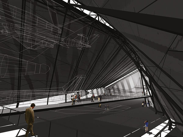
The museum will be an iconic steel addition to the Mersey waterfront
A new landmark is taking shape on Liverpool’s waterfront. NSC takes the ferry across the Mersey to visit the city’s new cultural museum.
FACT FILE: Museum of Liverpool
Main client: National Museums Liverpool
Architect: 3XN and AEW
Structural engineer: Buro Happold
Main contractor: Pihl Galliford Try
Steelwork contractor: Caunton Engineering
Steel tonnage: 2,100t
Project value: £65M
Sydney has its opera house, Bilbao its Guggenheim art gallery. Now, Liverpool is joining them with its own iconic symbol of cultural tourism, a radical new history museum that will sit alongside some of the city’s best known buildings on the historic Pier Head.
The site, on the eastern shore of the River Mersey, is home to what are known as the ‘three graces’, three landmark buildings constructed in the first 15 years of the 20th century – the Royal Liver Building, Cunard Building and the former offices of the Mersey Docks and Harbour Board. Liverpool has long wished to add a ‘fourth grace’ on the waterfront, and the new Museum of Liverpool meets that aspiration.
It is a striking building, a low, stone and glass-clad structure with sweeping “wing” roofs and huge glass picture windows at either end. On plan, it occupies the space of a partially closed X, and is symmetrical about the diagonal axis.

Artists impression of the completed museum

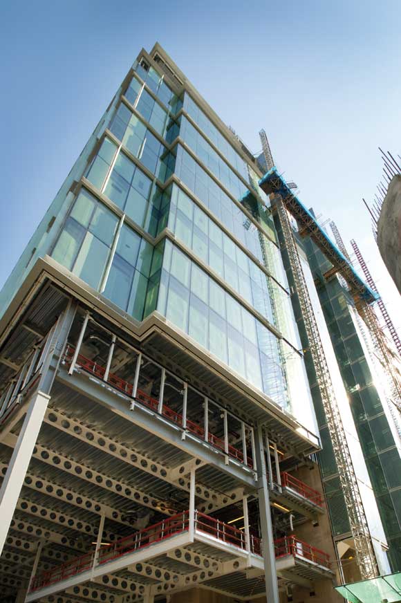
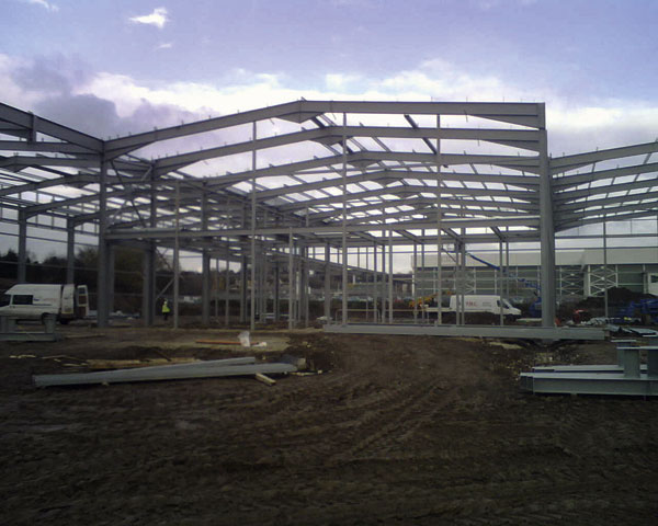
Clear spans and a complex geometry are the main features of the steel frame

Complex geometry are the main features of the steel frame
Inside will be three levels of exhibition space built around a full height central atrium dominated by an elliptical spiral staircase. Although the museum will predominantly be clad in stone, natural light should flood into the building both from a large skylight above the atrium and from the glazed north and south elevations on the second floor.
The concept for the building came from Danish architect 3XN, although Manchester-based executive architect AEW has now taken over responsibility for delivering the design. A joint venture of Danish construction company Pihl and UK contractor Galliford Try has a £41M to build the museum, with the total cost of the project – including fit-out – set at £65M.
Engineering consultant Buro Happold has the task of turning the architect’s vision into a workable structure. “It’s a very complex, unconventional form,” explains the company’s Structural Engineer David Taylor. “The client was looking for large, open spaces, and the architect has come up with a scheme which provides this, and within a very unusual form.”
Those clear spans are at their most significant on the second floor, where there are two 40m long, column-free main galleries – one at either end -with the beams above spanning 28m across the width of the structure. “The clear spans required were achieved by the use of a steel frame,” explains Mr Taylor.
There is a total of 2,100t of steel in the building’s main structure, which has been designed to resist not just self-load and the weight of exhibits and visitors, but also the substantial horizontal and uplift forces from the high winds that affect the Mersey’s shores. All of this load is taken into the ground via a 4m deep reinforced concrete raft structure, consisting of top and bottom slabs joined by a series of vertical walls.
“The raft solution was arrived at because of the various constraints on the site,” explains Buro Happold Structural Engineer Matt Barron. “With a building of this size, piling would often be the first thing you would look at, but the Mersey Rail Tunnel runs right under the building and so piling had to be ruled out. The intention is to minimise the net increase in loading above the tunnel. Instead, the design of raft ensures the load is spread as much as possible, and so that the weight of building replaces the weight of soil that is excavated.
“The objective of the raft is to withstand all the superstructure loads and act as a beam, so the reinforcement has been designed to take the different bending moments that the superstructure puts on it,” he adds.
The exact shape and plan area of the raft were arrived at by analysing the bearing pressures from the superstructure loads, and it extends beyond the footprint of the building itself in order to take the large point loads at each corner created by the 15m cantilevers of the main second floor galleries. Uplift loads on the foundations are up to 5,000kN and vertical forces into the main cantilever columns are 16,000kN.
Buro Happold’s structural design splits the building into three sections – the centre and the two ends – with movement joints separating them. The split is necessary as there is the possibility of differential thermal expansion across the length of the structure. Although vertical forces can be transferred across the joints, the frame has been designed to ensure horizontal and rotational movement is contained within each section.
The centre section of the building is stabilised by two circular concrete lift cores, while the horizontal stability at the two ends comes from one lift/stair core and a shear wall in each section to combat torsional rotation from the prevailing winds. Stability also comes from the composite metal deck and in situ concrete floors – particularly the second floor, which acts as a diaphragm, providing restraint for the cantilever sections of the building.

Steelwork is connected to circular and square concrete cores

The completed project will be Liverpool’s ‘fourth grace’
The client’s understandable demand for clear, open spaces has resulted in some very large steelwork sections being fabricated and supplied by steelwork contractor Caunton Engineering. The roof above the second floor galleries is supported by Westok cellular beams spanning 28m, and there are also two 2.3m deep x 26.5m long plate girders in the central section of the building. “They sit very close to the movements joints, and carry loads from the plant room roof and also from the roofs of the two outer sections,” explains Caunton Director Allan Younger.”
The girders are supported at one end by the circular concrete lifts cores and at the other by articulated columns that are held in place by 80mm diameter pins. Originally there were to be four of these massive plate girders, but two were taken out of the design during a value engineering exercise prior to construction when the client accepted a design change that involved introducing four columns into the central atrium. “That allowed us to take out two of the plate girders and create a lighter structure in the roof,” explains Mr Taylor.
The remainder of the frame involves an extremely wide range of steel sections – from 127 x 76 beams right up to 1,016 hollow sections. There are also some cold rolled sections used as purlins in the roof and to support services below the second floor. “I wouldn’t be surprised if there is every section in the book somewhere in the building,” says Mr Younger. But, he explains, the lack of repetition in the building is not a problem when it comes to manufacture. “We operate a just in time system of making erectable loads of steelwork, so we don’t batch manufacture too much. On this job we’ve broken it down into the three phases, and then broken those into bite sized chunks, which are then designed, drawn and manufactured in the same sequence.”
Pihl Galliford Try’s construction sequence involves working from the centre outwards. “That is based on Buro Happold’s design philosophy of trying to build symmetrically about the tunnel,” explains the joint venture’s Project Manager Christian Lundhus. “We did that with the raft, and now we’re doing it with the structural steel.”
Steel erection started in November, and has now reached the stage where Caunton is ready to fix the cantilever sections on either end. These are made up of triangulated braced bays on either side, with a single beam spanning between them top and bottom. The bracing for these bays is made from 500mm deep x 30mm thick double plate sections.
Until construction is complete and the walls are cast, the four corners of the structure must be propped on temporary steel towers supported by piled foundations. The towers will be fitted with 400t jacks that can be used to counteract deflection effects during construction. But once the floor is cast, deflection is anticipated to be no more than 20mm.
In the permanent condition, the load from the cantilevers comes back through the triangulated truss arrangement into columns that take the tension load straight down to the base of the raft. This has been achieved by installing steel plunge columns into the concrete during construction of the raft foundation.
“Two sections of column were cast into the foundation very accurately, and a cap plate was left projecting out of the concrete for connection of the column above,” explains Mr Taylor. “Accuracy of the casting was essential as the main columns sit on top.”
Caunton’s directly employed team of specialist erectors are set to finish on site in May in a contract that includes not just the main frame but also support steelwork for both internal and external finishes. Pihl Galliford Try is scheduled to complete construction next year, with the new Museum of Liverpool due to open at the end of 2010.