Projects and Features
Going over ground
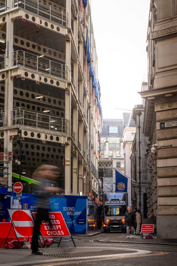
A new entrance to a City of London Underground station has created space for the construction of a nine-storey commercial development.
FACT FILE
10 King William Street, London
Main client: Helical, Places for London joint venture
Architect: Fletcher Priest Architects
Main contractor: McLaren Construction
Structural engineer: Robert Bird Group
Steelwork contractor: Bourne Steel
Steel tonnage: 1,650t
Recognised as one of the busiest underground stations in the capital, Bank Station has recently been upgraded in order to ease congestion and make wayfinding between the various lines easier.
Among the improvements, a new station entrance has been created on Cannon Street, allowing better access to Northern Line and DLR (Docklands Light Railway) platforms, while also providing a direct street-level link to the nearby mainline railway station (Cannon Street).
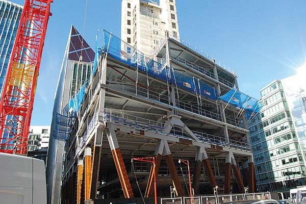
Completed in 2023, the new entrance includes a single-storey ground-level concrete box, which was designed to be part of an over-station development by having a series of plinths, sat in specific locations to support steel columns and their loadings.
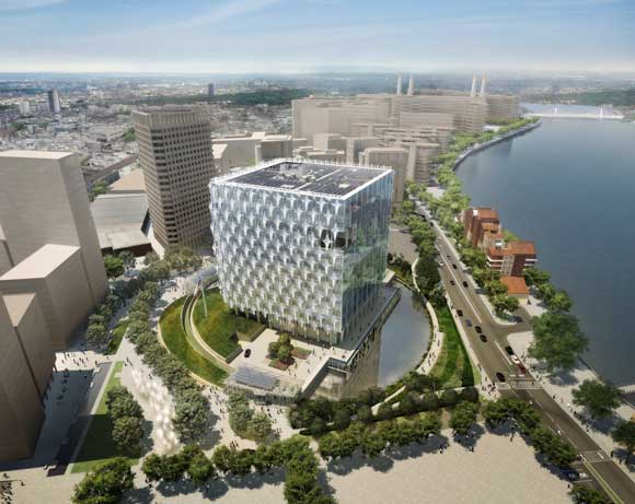
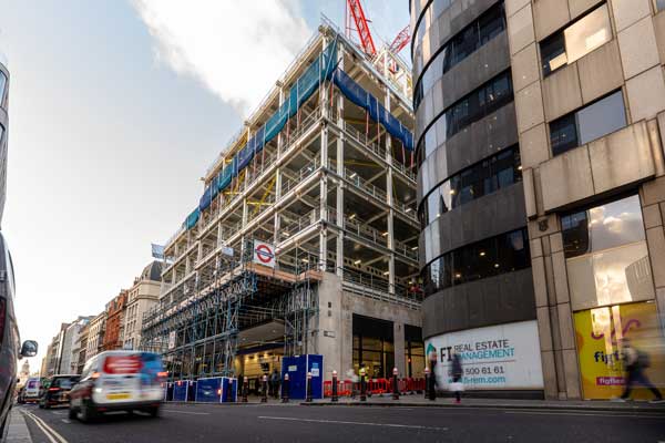
Currently under construction, the over-station scheme is known as 10 King William Street, as its main entrance is on the plot’s northern boundary. The island site, which was cleared before the station works began, is also bounded by Abchurch Lane to the west and Nicholas Lane to the east.
The new building is a nine-storey steel-framed structure delivering 13,000m² of office space, 2,212m² of terracing, alongside 594m² of retail and occupier amenity provision.
Matthew Bonning-Snook, Chief Executive of Helical, says: “This facility highlights the confidence in the London office market for ‘best-in-class’ assets, rich in tenant amenity, which will be delivered into a supply constrained City Core market where we are seeing strong rental growth and increasing momentum behind a more comprehensive ‘return to the office’.”
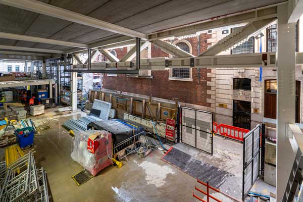
The station entrance occupies approximately half of the site’s footprint and so the over-station office development spans over the box, creating a design where the new building’s floorplates extend to their maximum size from first floor upwards. The lower levels – basement, ground and mezzanine – are sat next to the station box.
“To isolate the internal warm structure of the new development from the cold structure of the station box, which is open to the elements, the connecting steelwork includes thermal breaks,” explains McLaren Construction Project Director Dermot Keane.
“The walls that interface with the station box are also thermally lined.”
As well as the box, the new building is also founded on a 1.8m-thick raft foundation, positioned under the single-storey basement and constructed at the same time as the station entrance. This foundation solution was chosen because the site’s location, situated above numerous tunnels and shafts, would have made the installation of piles extremely challenging.
The steel frame starts at ground floor and gains the majority of its stability from centrally-positioned concrete core, which is sat on both the station box and the raft foundations.
“The core is placed in the optimum position to allow the office floorplates to have the desired long-span design,” says Robert Bird Group Director Alejandro Cruz.
Chosen as the most efficient solution, a series of Westok cellular beams, up to 20m-long, radiate outwards from the core.
Westok London Resident Engineer James Way, comments: “We continue to see growth in demand for clever low-carbon design solutions in the London commercial sector and we have a number of live sites in the City right now, featuring clear-span beams.
“At 10 King William Street, the lightweight Westok beams typically have a regular arrangement of 400mm-diameter cells, and longer-spanning members have been cambered to significantly reduce construction stage deflection.”
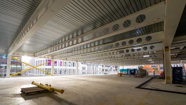
The beams accommodate the building services within their depth and support metal decking and concrete topping to form a composite flooring solution for the majority of the floorplates.
Around the core on each level, there is a small area of precast flooring, chosen as it creates a smooth soffit, which will be left exposed.
Also, left exposed in the completed building are the majority of the internal columns. Creating a modern industrial-looking environment for the future tenants, the columns are painted with a high-specification coating.
Fabricating, supplying and erecting 1,650t of steelwork for the project, subcontractor Bourne Steel completed its package in January.
For its steel erection programme, Bourne was able to make use of the site’s two tower cranes, which are positioned within the footprint of the building and on top of the core respectively.
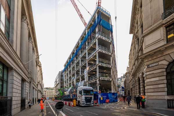
Both cranes are able to reach all parts of the project, as well as lift steelwork from the delivery trucks when they arrive at the pit lane.
Working in central London, space is always at a premium and this project has been fortunate to have gained permission to close one side of King William Street, for its invaluable delivery pit lane.
Starting the steel erection programme in and around the core, one of the earliest elements to be installed was also one of the heaviest. Positioned at the underside of first-floor, along the western elevation, a 24m-long × 2m-deep truss, weighing 30t, forms a column-free space for the building’s loading bay entrance.
In order to keep the weight within the capacity of the tower crane, the truss was delivered to site in three sections. The pieces were then individually lifted into place and bolted together, while being supported on temporary props.
Prior to delivering the steelwork to site, and to make sure the truss fitted together exactly, Bourne Steel undertook a cloud point survey and trial erection at its fabrication yard.
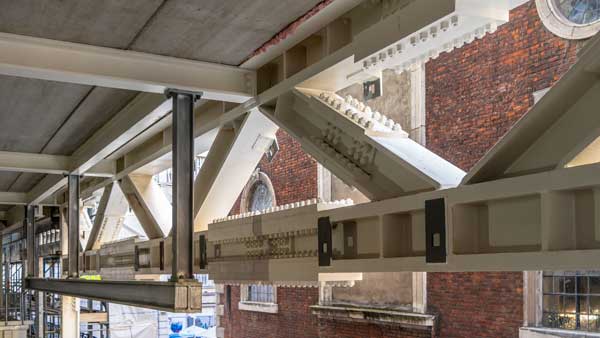
Next to the loading bay entrance, the steelwork on the south-western elevation will support, via a secondary steel frame, a re-used Portland stone and red brick façade.
Dating from the 1880s and originally from one of the site’s previous buildings, which were demolished before the station entrance works began, the façade was carefully dismantled, stored away from site and will be installed later in the programme.
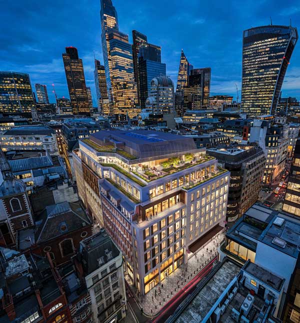
The uppermost three office floors feature terraces, providing the tenants with outdoor breakout spaces with views of St Paul’s Cathedral. Large plate girder transfer beams, weighing up to 16t, support the underside of these floors and the inset column lines.
Above the uppermost office floorplate, the steel frame extends to include a plant deck, which will be fully enclosed by a roof structure. Formed with a series of long-span rafters, the clad structure will hide the plant equipment and improve the view for the building’s many neighbours.
McLaren will hand over the completed 10 King William Street project in the fourth quarter of 2026.
Plate girder behaviour
At 10 King William Street, large plate girder transfer beams weighing up to 16t, illustrate the scale and structural importance of this feature in multi-storey developments. Their behaviour is often dominated not by bending, but by shear. Yigit Ozcelik of the SCI comments on why this aspect of design deserves careful attention.
With deep plate girders, slender webs are almost unavoidable if the member is to remain efficient in weight and embodied carbon. However, once the web slenderness exceeds the elastic critical limit, shear resistance is no longer governed by yield strength alone. Instead, stability will dominate, and designers must explicitly consider shear buckling and post-buckling behaviour. Eurocode design recognises this clearly. BS EN 1993-1-5 introduces the concept of tension field action, although not explicitly stated, allowing a slender web to develop significant post-buckling resistance, provided that the flanges and transverse stiffeners are capable of anchoring the diagonal tension field.
This post-buckling capacity cannot be taken for granted, as it requires strict boundary conditions. If the flanges are too flexible, or the stiffeners too widely spaced, the web cannot develop a tension field and the theoretical resistance will not be achieved in practice. Clause 5 of BS EN 1993-1-5 therefore requires consideration of the stiffness of transverse stiffeners. These stiffeners are not secondary detailing items – they become primary structural components.
Designers sometimes underestimate the importance of transverse forces and bearing in plate girder transfer beams. Concentrated loads from columns introduce local compressive stresses that interact directly with shear buckling, often requiring closely spaced stiffeners or thicker webs. The interaction rules in Clause 7 of BS EN 1993-1-5 make it clear that shear, bending, and transverse forces cannot be treated independently in slender webs.
From a practical perspective, fabrication and erection also influence shear performance. Large unstiffened panels may look efficient, but can produce very slender web panels with very low elastic buckling resistance. Conversely, excessive stiffening increases fabrication complexity and welding. The optimal solution lies in balanced design, where web thickness, stiffener spacing and stiffness are considered together as a system.
Plate girder transfer beams are high-consequence elements where failure is not an option. By explicitly designing for shear buckling and properly mobilising tension field action in accordance with BS EN 1993-1-5, engineers can design slender webs without compromising safety. In this way, shear buckling becomes a controlled response rather than a failure mode, allowing plate girder transfer beams to efficiently carry extreme column loads while minimising material use and embodied carbon.