Technical
Experimental behaviour of a steel structure under natural fire
A full scale European collaborative test has shown that the fire performance of a steel building was better than that predicted by calculations or design codes.
Current design codes for determining the fire resistance of structures are based on isolated member tests subjected to standard fire conditions. Such tests do not reflect the behaviour of a complete building.
The performance of real structures subject to real fires is often much better than that predicted from standard fire tests on isolated members due to structural continuity and the provision of alternative load paths.
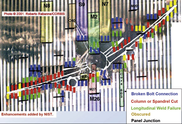
The high cost of full-scale fire tests and the size limitations of existing furnaces has limited studies to isolated element tests. However, the failure of the World Trade Centre on 11th September 2001 and, in particular, of building WTC 7, alerted the engineering profession to the possibility of connection failure in fires.
The aim of this project was to investigate the global structural behaviour of an 8-storey steel framed building subjected to a design fire in one of its compartments. The results presented include the temperature development within structural elements, the distribution of internal forces and the behaviour of the composite slab, beams, columns and their connections. The results suggest that the inherent fire performance of a lightly reinforced composite slab is significantly higher than calculated using traditional design methods, and confirm the conservatism of the fire engineering approach given in the Eurocodes.
The development of the Building Research Establishment’s facility at Cardington provided the construction industry with the opportunity to carry out research projects that included full-scale fire tests. It contains three experimental buildings, including an eight storey steel structure.
The steel building simulates a real commercial office in the Bedford area and was designed to comply with British Standards and the Structural Eurocodes.
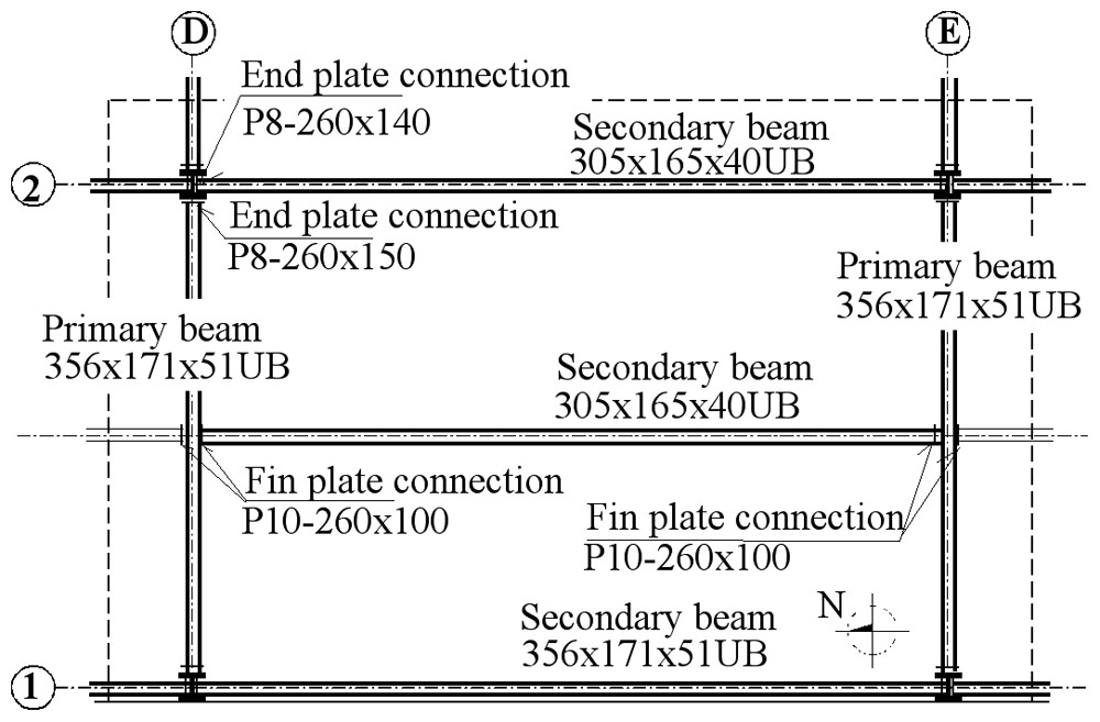
It consists of a steel frame with steel and concrete composite floors. It is eight storeys (33m) high and is five bays wide and three bays deep. The building is a non-sway structure with a central braced core containing a lift shaft and a braced core at either end. The connections consist of flexible end plates for beam-to-column connections and fin plates for beam-to-beam connections.
The building was designed for a dead load of 3.65 kN/m² and an imposed load of 3.5 kN/m². The floor construction consists of a profiled metal deck acting compositely with lightweight in-situ concrete and incorporates anti-crack mesh.
Test programme
The fire test was carried out in a centrally located compartment of the building, enclosing a plan area of 11m by 7m on the 4th floor (Figure 1).
The load was simulated using sandbags, each weighing 1100kg. The sandbags represented 100% of the dead load other than the self-weight of the structure and 56% of the live load. The load was chosen so that local collapse of the floor would be expected under fire, based on analytical and FE simulations.
The fire load was provided by 40 kg/m² of wooden cribs covering the floor area of the compartment. The fire compartment was bounded with three layers of plasterboard. In the external wall the plasterboard was fixed to a 0.7m high brick wall. An opening 1.27m high and 9m long simulated an open window to ventilate the compartment and to allow the behaviour of the various structural elements to be observed. The thermal load and the dimensions of the opening were designed to be representative of a fire in an office building. Preliminary calculations predicted a hot but short duration fire.
The columns, external connections and connected beams were all fire protected with 15mm of Cafco300 vermiculite-cement spray.
Sections exposed to the fire were 356 x 171 x 51 UB, 305 x 165 x 40 UB, 305 x 305 x 198 UC and 305 x 305 x 137 UC. Connections were a cruciform arrangement of a single column with either three or four connected beams respectively, to the column flange and web.
Instrumentation
Instruments measured the temperature, the distribution of internal forces, and the deflected shape of the floor and the main structural elements.
Some 133 thermocouples were used to monitor the temperature in the connections and beams within the compartment, the temperature distribution through the slab and the atmosphere temperature within the compartment. Another 14 thermocouples were used to monitor the temperature of the protected columns.
High temperature and ambient temperature strain gauges were used to measure stresses and deformations. High temperature gauges were used in the connections only. In the protected columns and unexposed elements, 47 ambient temperature strain gauges were installed. 25 vertical displacement transducers were installed directly above the fifth floor to measure the deformation of the concrete slab.
12 additional transducers were used to measure the horizontal movement of the columns and the slab. 10 video cameras and two thermal imaging cameras recorded the fire and smoke development, the structural deformations and the temperature distribution with time.
Observations
During the test the predicted local collapse of the structure did not occur. The maximum recorded compartment temperature near the was 1107.8°C after 54 minutes, compared with a prediction of 1078°C in 53 minutes.
The maximum recorded steel temperature of 1087.5°C occurred after 57 minutes, on the bottom flange of beam DE2 in the middle of the section. A temperature of 1067°C after 54 min was predicted.
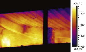
Figure 3: Fin plate connection D1-2 recorded by thermo imaging camera during heating after 58 minutes of fire
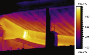
Figure 3 : Fin plate connection D1-2 recorded by thermo imaging camera during cooling after 92 minutes
Measurements of the temperature in the connections showed that in the heating phase, the connection temperature is significantly lower than that of the remote bottom flange, which is usually the critical element that defines the limiting temperature of the beam. In contrast, the connections cool more slowly than the beam. Using the thermal cameras it was possible to observe this effect, which is shown in figure 3.
At the maximum temperature, the joint temperature was around 200°C lower than the limiting temperature of the beam.
The maximum deflections exceeded the range (1000mm) of the displacement transducers, but from the video cameras on the fifth floor it was possible to calculate the maximum vertical displacement which was about 1200mm.
Local buckling of the beam lower flange was one of the main failure mechanisms. It is observed in the lower beam flange and web adjacent to the connections. This local buckling occurred during the heating phase after about 23 minutes, due to the restraint to thermal elongation provided by the adjacent cooler structure. As the temperature and the associated deformations increased, the shear resistance of the beam web was also reached.
The formation of a plastic hinge in the beam cross-section next to the protected zone was one of the main observed mechanisms in beam D1/2. This hinge is induced by lateral-torsional buckling during the heating phase, due to the restraint to thermal elongation provided by the adjacent protected section. This behaviour is associated with the local loss of stability in the bottom flange.
Buckling of the column flange in compression was observed in the major axis beam-to-column connections.
Behaviour of connections
Fracture of the end-plate along the welds was observed, caused by the horizontal tensile forces during cooling of the connected beam under large rotations associated with the flexible end-plate joints. The fracture occurred along one side of the connection only.
Elongation of the holes in the beam web in the tension/compression part of the fin plate connection was due to the associated large rotations. The fin-plate remained intact.
Composite Slab Behaviour
Fracture in the concrete slab was observed with a large crack propagating from the face of the column flange parallel to the beam D-E2. This crack developed due to tension in the concrete slab, along the weak zone in the composite beam-flange extremity. Secondary cracks occurred perpendicular to, and continuous across, the connections on both sides of the slab. The maximum vertical displacement occurred along a line of overlapped mesh reinforcement without adequate attachment, so that the slab behaved as if unreinforced.
The cameras above the fire compartment recorded loss of integrity in the concrete slab after 54 minutes, by a punching mechanism due to tension in the slab in the edge compartment.
Conclusions
Although temperatures in excess of 1000°C were achieved in the main supporting steel members, and displacements of approximately 1200mm were observed in the composite floor, collapse of the structure was not reached. It should be noted that the applied mechanical load was higher that the typical serviceability condition. This suggests that the inherent fire performance of a lightly reinforced composite slab is significantly higher than calculated using traditional design methods. The test results support the concept of using unprotected internal beams with protected perimeter beams and columns as a viable fire engineering solution for steel framed buildings with composite floors.
The test also confirmed the conservatism of the fire engineering approach given in the Eurocodes. The calculated values gave conservative predictions of the temperature in the fire compartment, the transfer of heat into the structure and connections and of structural behaviour.
This is a condensed version of a paper which presents the results of a collaborative research project (Tensile membrane action and robustness of structural steel joints under natural fire, European Community FP5 project HPRI – CV 5535) involving the following organisations: Czech Technical University (Czech Republic), University of Coimbra (Portugal), Slovak Technical University (Slovak Republic) and Building Research Establishment (United Kingdom).
This project was supported by a grant from the European Community FP5 HPRI – CV 5535 and COST C12 and this paper has been prepared as part of the Czech Grant Agency project 103/04/2100.
The full paper is available at www.steelconstruction.org
AUTHORS
- Wald, F.,
- Simões da Silva, L.,
- Moore, D.B.,
- Lennon, T.,
- Chladná, M.,
- Santiago, A.,
- Beneš M.,
- Borges, L.


