50 & 20 Years Ago
Cross Harbour Tunnel: Hong Kong
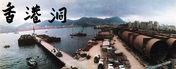
One of the most interesting submerged tube tunnels to have been built in recent years was the cross-harbour tunnel at Hong Kong. It is the longest of its type· in the world and was placed in busy waters of variable density and subject to typhoons. These notes briefly describe the design and the method of construction.
In the nineteenth century Hong Kong island was almost totally devoid of human population;· in 1945 the numbers had fallen from former heights to around 600,000; today the staggering total is over 4,000,000. Growth at that rate would present problems enough in any environment but they were intensified at Hong Kong as space is limited and also because the Colony is divided into two main parts Victoria on the island and Kowloon on the mainland. Communications between the two were by ferries, some for passengers only and others carrying vehicles. But even at their best these are not adequate to maintain a smooth flow of traffic and in difficult weather the service can cease altogether. Some idea of their importance can be gathered from the fact that in 1970 the ferries carried 16,700 vehicles and 655,000 pedestrians daily. It had been obvious for some time that a better link was required between the island and the mainland and a number of discussions had been held on the subject. The Government of Hong Kong decided in 1957 that it could not promote any scheme, but it did encourage the idea of a private development which could recover its outlay through charging tolls. Consequently, in 1959, a group of Hong Kong businessmen founded the Victoria City Development Co. Ltd with the intention of establishing a permanent link across the harbour. They commissioned Scott Wilson Kirkpatrick & Partners to carry out a feasibility study on the traffic flow on the basis of which design studies were begun.
At this stage both tunnels and bridges were being considered and Freeman Fox & Partners joined in for their special bridge experience. When designs had been prepared it was found that either type of crossing was possible with the bridge being slightly more economical. The choice was made therefore on the effect these structures might have on other interests. Since typhoons occur from time to time during which ships have been known to break loose from their moorings it was first feared that this would prevent a bridge being built. However, the shipping difficulties were overcome but the bridge scheme had to be abandoned as the area is sometimes crossed during emergency procedures by low-flying aircraft. Following these investigations the Hong Kong Government approved a tunnel scheme in 1966. Permission was given to the Hong Kong Cross-Harbour Tunnel Co. Ltd, successors to the Victoria City Development Co. Ltd, to build a dual two-lane tunnel financed from tolls.
The original design on which tenders were invited called for twin reinforced concrete tubes of roughly rectangular cross-section but alternative proposals were invited from tenderers if they wished. The contract was won by a consortium headed by Costain International Ltd on the basis of an alternative design featuring twin circular cross-section steel tubes. This design had been prepared by Parsons Brinckerhoff Quade & Douglas of New York.
The tunnel has a 22ft wide two-lane carriageway in each tube; at the Kowloon end and after emerging to the surface the road width increases to 215ft in order to accommodate the fourteen toll booths, six of which can be reversed for tidal flow. There is 16ft of clear headroom throughout the tunnel and gauges have been installed to prevent exceptionally tall vehicles from entering. The total length of the tunnel is 6,088ft from portal to portal and of this length 5,256ft is submerged. The exit gradients are about 1 in 16 so additional climbing lanes have been provided for slow vehicles. Buildings housing ventilation equipment are located at both ends of the submerged tunnel.
With any design of submerged tunnel buoyancy is clearly important, and this aspect was made particularly difficult at Hong Kong as the salinity of the water varied greatly depending largely on the state of the Pearl River. In order to keep a close control on the buoyancy of the tunnel units the water density was measured for each sinking operation. Construction and erection loads also required very careful consideration in order to avoid overstressing in the steel tubes. Until the internal linings had been completed it was important to avoid highcompression stresses in the top of the tube. When floated from the slipway the weight of the end bulkheads caused the tubes to be in a reverse bending condition so that only tension developed in the upper sections. Subsequent concrete lining was carried out in such a way as to ensure that no large compressive stresses could occur in the steel plates. Possible damage from dragged anchors from ships out of control in typhoons has been prevented by the rock cover to the tunnel. Furthermore, the tunnel has been designed to withstand the weight of any ships that might sink on to the tubes.
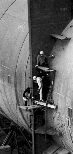
The steel units were fabricated on site by Redpath Dorman Long from material shipped from the BSC. The plates were 36ft x 6ft x ¾in and after flattening they were squared and accurately cut to size with edges prepared for welding by gas cutters. They were then welded in sections 35ft 6¾in x 11 ft 5in and rolled to the correct radius. Elsewhere 5in x 7in Tee stiffeners were curved to shape and welded together to form rings. The plates were welded to the rings to make cans 11ft 5in high x 34ft diameter. These were turned through 90″ and assembled together in sets of five to make a length of 54ft 5in. Circumferential seams were welded inside and outside by machine. The tubes were then assembled into complete units with diaphragms; all welding at this stage was manual. Assembled lengths varied between 324 and 374ft. The reinforcement for the linings was next added following which the sections were moved to the top of the slipway where the concrete keel was cast and the prefabricated watertight bulkheads were welded to the ends of the tubes. After completion of this work and a number of other operations the units ‘weighed about 6,000 tons of which about 1,500 tons was structural steel. The units were then floated to the fitting-out jetty where ballast concrete was placed between the tubes and the internal concrete lining was cast, the total addition being about 16,000 tons. While the concreting was being completed a trench was dredged out so that it finished about 2ft below the final founding level. This trench was then filled to bedding level with crushed stone which was screeded to levels. The same machine used for these operations was also employed in placing the assembled units any variation in sea level being overcome by anchor weights which held the rig until the pontoons were almost awash. The tunnel units were then placed after having been ballasted to about 400 tons of non-buoyant weight. Further concrete ballast was added after each unit was in position. Attached to the end bulkheads were cylindrical plates which overlapped on adjacent ends. The gap between them was caulked with timber and filled with concrete. The gap between bulkheads was then cleared of water, sealing plates were welded between the overlapping cylinders and the internal concreting was finished. All that remained was to place the earth and rockfill protective covering.
CREDITS
Consulting Engineers
Scott Wilson Kirkpatrick & Partners
in association with
Freeman Fox & Partners
Architects to the Engineers
Robert Matthew, Johnson-Marshall & Partners
Main Contractors
A consortium of:
Costain International Ltd
Raymond International Inc.
Paul Y. Construction Co. Ltd
Steelwork Subcontractor
Redpath Dorman Long (Contracting) Ltd