Projects and Features
Cantilevered for success

Steelwork starts at ground level and is based around a large 9m x 16m grid.
A new commercial development in Glasgow has been highly engineered to provide both long internal spans and significant elevation cantilevers, reports Martin Cooper.
FACT FILE: 29 Wellington Street, Glasgow
Architect: 3D Reid
Main contractor: BAM Construction
Structural engineer: BAM Design
Steelwork contractor: BHC
Steel tonnage: 1,100t
The credit crunch may be biting hard in some construction sectors – most notably the residential and commercial markets – but in Glasgow there are still a number of high profile jobs on the go, judging by the number of tower cranes visible across the city’s skyline.
One of the most visible projects is a new 10-sto- rey office development rising up on the plot of 29 Wellington Street in the city centre. This steel framed building is replacing a concrete framed structure which was built in the late 1960s, although the new build now includes a one level basement car park.
BAM Construction in its role as management contractor has been on site since mid-2007 and began by demolishing the original building.
Once this was completed a series of 12m deep cantilevering permanent exposed sheet piles were installed around the site’s perimeter, in lieu of contiguous or secant bored piles as suggested by BAM Design.
“This saved weeks of construction time when compared with the alternatives,” explains John Keys, BAM Construction’s Project Manager. “This greatly facilitated the basement excavation and therefore steelwork erection could commence earlier.”

The tight and confined city centre site.
The original architectural concept was based on a standard 9m x 8m central column grid. However, BAM Design suggested losing a line of columns and this resulted in a far more desirable 9m x 16m grid pattern.
This large grid pattern is based around four large 356 x 406 x 634 columns, positioned around 3.5m from one elevation, which also form part of a four-bay full building height moment frame. These columns are 8.9t each and extend from ground floor all the way to roof level. They were installed in three sections: 2 x 13m long columns and then one 7m long member for the eighth floor to tenth floor phase. The column splices were designed by steelwork contractor BHC, based on BAM Design’s connection concept featuring countersunk bolt heads, maximising net lettable area.
Structurally one of the main features of the building are its feature cantilevers, one at 3.4m and the other reaching a maximum length of 4.4m. To control the end displacement, the 16m back span beams were designed as continuous non-composite with regards to strength, while deriving benefit from composite action with regards to deflection.
“These cantilevers support a unitised glazing system, which stipulates highly onerous deflection criteria of less than 10mm both horizontally and laterally,” explains Mohammad Ziauddin, BAM Design Project Engineer. “Furthermore, the building is designed for multiple occupancy, which means that the cantilevers are subject to movement up or down relative to the floor above and below.”

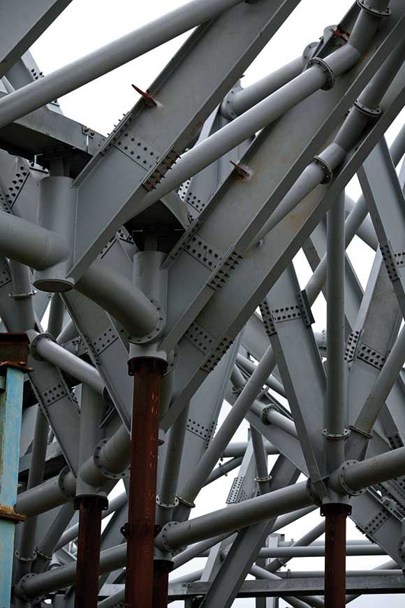
Feature tubular bracing.
Westok beams ranging from 480mm deep to 580mm deep have been used for the long internal spans and cantilevers. This not only provided the benefits of weight efficiency gains and complimentary pre- cambering, but also an integrated distribution of lateral services within the structural zone, giving added flexibility for future multi-tenancy.
Lateral stability of the steel framed structure is achieved by the use of both steel cross bracing in stair/lift cores as well as moment frames. One elevation has cross bracing comprising 219mm diameter tubular sections in full view as an architectural feature. The lateral forces are transferred to the vertical bracing systems via the concrete floor slabs by a diaphragm action. The horizontal displacement of the building has major significance to the design of the glazing system, due to the potential for racking under wind loading.
“Many projects of this type would have gone with concrete shear walls, but we decided on steel cross braced walls which are easier to erect and much quicker, as they go up with the main steel frame,” adds Mr Ziauddin. “There was no waiting around for the concrete cores to be completed before steelwork erection could begin.”
The entire superstructure was modelled by BAM Design in CSC’s Fastrak Building Designer with lateral loads such as NHF and wind being applied automatically. The Westok beams were also modelled in Fastrak Building Designer but designed using SCI’s specialist Cellbeam software. All floor plates are based on the typical second floor level which features the largest floor area. Other floors are simple variations on this level, featuring cut-outs and recesses.
For the steel erection BHC’s initial phase was the basement to the second floor. Once this was completed and the floors decked, the second floor slab was cast and this allowed other trades to carry on working below while BHC put its cherrypickers on the slab to erect the floors up to level five.

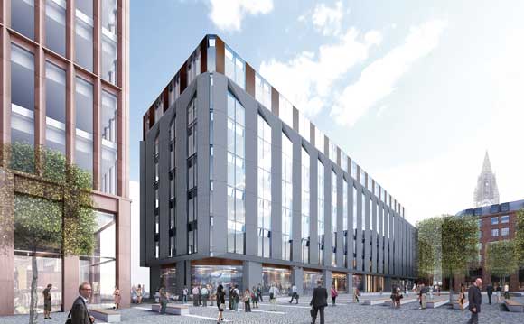
Impression of the completed building.
This methodology was then repeated for another two phases with BHC erecting steelwork from fifth floor to eighth floor, and then finally working off of the eighth floor slab to erect floors nine and ten.
Working in this way the entire construction team was able to erect and fit out the floors in a quick manner. Another consideration, and one which surfaces on many inner projects was the lack of available space for on-site materials storage.
“We had to bring steel to site in 15t loads and lift them immediately to the floor we were erecting off,” explains Jim MacDonald, BHC Project Manager. “In this way we didn’t overload the on-site tower crane’s capacity and we were able to erect each load as it came in.”
“It was all down to planning the logistics of the job well ahead as a team,” sums up Mr MacDonald. Keeping ahead of the game and thus completing the project on time are all key reasons why the design team says they chose their methodology.
29 Wellington Street is due for completion by the third quarter of 2009.