Technical
Blowing – our way
Alastair Hughes of the SCI pieces together the impact of Eurocode wind actions on the UK, in comparison with BS 6399-2.
Part One: Assessing wind pressure for the site
Introduction
Regrettably, no single publication encapsulates the new UK wind regime. EN1991-1-4, the wind Code, its UK National Annex and its accompanying PD6688-1-4 will all be on the desk of the properly equipped structural designer, who might have expected something more user-friendly in return for £544. It will take time and effort to appreciate its merits.
In theory, National Annexes reflect differences of climate or way of life, and the vision for the future is that they will be phased out. (The climate will never be harmonized, but the Code could include an atlas of wind maps as already done for snow.) Today’s reality is that National Annexes reflect a lack of agreement amongst the drafting committees. EN1991-1-4 contains over 50 invitations to determine a parameter or choose between alternative methods. The UK committee exercises a lot of national choice, not merely fine tuning parameters but effectively overriding sizeable chunks of Code. It is done from the best of motives, which the committee is conscious of the need to explain. This is where PD6688-1-4 comes in, as NAs are not permitted to give reasons. The PD (BSI ‘published document’) fills this gap, and its mission extends to include code-like clauses of its own, as a lifeboat for BS6399-2 material. For practical, if not legal, purposes the PD may be accorded near-code status.
This article concentrates on what is different (from BS6399-2) in the UK’s new regime (Code, NA and PD taken together). Attention is confined to the quasi-static assessment that controls lateral design of buildings of relatively modest height.
What hasn’t changed?
The end result, ‘characteristic’ wind force acting on the building, is identically defined. It is the short duration (gust) force with a 0.02% annual probability of exceedance (formerly described as a return period of 50 years). Although ‘flipping’ between codes is generally frowned upon, in this instance it should be acceptable to use the result as input for a BS5950 design calculation if wished.
q, the key intermediate calculation result, is also the same, although referred to as velocity pressure in preference to dynamic pressure (or stagnation pressure) and now given subscript p (for peak).
The 2010 UK wind map

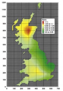
Map from CLG’s wind speed calibration study. Red alerts Highlanders to significant upward reappraisal of design wind; green is downward
The most obvious change is that the new wind map plots 10 minute mean velocity instead of hourly mean. Progress towards harmonization, but technically of limited significance; wind speeds have been factored up by an empirical 6% and gustiness (in Code parlance, turbulence) factored down to compensate. The rebasing should not obscure genuine improvements in the new map, based on 30 years of records (previously 11). Statistically, this allows lower extreme values to be predicted without loss of safety.
There are regions with significantly increased or decreased wind. Hence the case for using the new wind Code even for a BS5950 design.

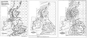
Evolution of the UK wind map: left to right, 1970 (gust speed at site level), 1995 (hourly mean at 10 m above sea level) and 2010 (10 min mean at 10 m above sea level)
Some new terminology
One familiar symbol swept away: wind pressure is no longer p (it becomes w) because p is for probability (though still allowed to represent pressure as a subscript). Symbols h for height, b for breadth (crosswind) and d for depth (downwind) are as before, only lower case.
Where wind is concerned, the axis convention is that x is the wind direction and z is upwards.
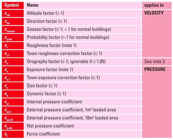
Here is a glossary of the c-factors (coefficients) which apply, to velocity or pressure:
”] An improvement to the altitude factorLike its immediate predecessor, the wind map ‘flattens the Kingdom’ in that its contours of velocity are for 10m above open country at sea level, irrespective of actual elevation. Results from the anemometer stations have been put through a process which is the reverse of the one to be applied by the Code user, of which the first stage is the altitude factor.Here the new regime offers an improvement by reformulating the factor as
calt = 1 + 0.001A[10/zs]0.2
where A is altitude and zs is the greater of 10 and 0.6h, both in metres.
If zs < 10, or optionally, the expression reverts to that of BS6399-2. For high buildings at high altitudes the reduction can be appreciable.
Orography in place of Topography
The substitution of ‘orography’ for ‘topography’ may displease those who care about the meaning of words. Orography is the geography of mountains, but relatively low hills and cliffs create ‘orographic’ situations for buildings.
Orographic situations are by definition those with mean wind velocity increased >5% by the landform. It would be necessary to perform an orography calculation to test against this criterion, but there are also some rules of thumb (not always easy to interpret).
With ‘significant orography’ the location factor s is the same as for significant topography in BS6399-2. But instead of modifying the altitude factor, sis used to derive a separate orography factor
co, representing the magnification of the mean wind velocity.
Orography does not increase the design (gust) velocity pro rata to the mean velocity. For buildings 50m and higher, there is a requirement to keep separate account of the gust intensity, consulting up to four graphs in the NA. Few of us will ever design a 50+ m building in an orographic situation, yet it is these graphs, Figures NA.3, 4, 5 & 6, which are given prominence. Buildings up to 50 m high are offered a simpler treatment, as for a non-orographic situation but with peak velocity factored [(co + 0.6)/1.6]. This uses Figures NA.7 & 8.
In orographic situations calt is calculated with A at the foot of the hill. In case non-orographic calculation (with actual site altitude) could deliver a higher result, duplicate calculations are called for.
Roughness and exposure – what’s the difference?
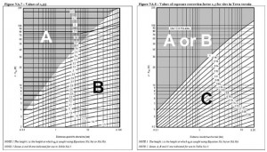
Both are factors to account for the effect on the incident wind of upstream terrain. But it’s one or the other. Roughness goes with the more elaborate treatment prescribed for 50+ m buildings in orographic situations. For lower buildings, and buildings in non-orographic situations, exposure factors are used.
Exposure factors apply to pressure whereas roughness factors apply to velocity. They are not directly comparable.
Terrain categorization kept simple
Exposure (or roughness) factors represent the reduction in wind speed due to terrain roughness upstream. Rougher terrain has more frictional effect, and it takes time, and distance, for the effect to be transmitted upwards. Only after well over 100 km is an equilibrium condition attained with a relatively uncomplicated relationship between wind speed and height.
In the base Code, as in distant memory, terrain subdivides into five categories ranging from sea to city, but the UKNA simplifies back to three: sea, country and town. For a country site, parameters determining the exposure factor (Figure NA.7) are distance from the shoreline and height at which wind is calculated (normally top of building). For an urban site, there is also an influence of distance from edge of town; the exposure factor is multiplied by a town terrain correction factor (≤1) from Figure NA.8.
Directional wind
In principle, options for directional treatment are as before. 30° sectors are commonly chosen, but not obligatory. Sectors may be oriented with the building, orography, shoreline or whatever.
Designers need not be disconcerted by the base Code’s recommendation against direction factors. It is of course conservative to ignore them and take cdir = 1.
Still to come
What the new regime describes as peak velocity pressure qp is directly comparable with dynamic gust pressure q of BS6399-2. It is an attribute of the incident wind, uninfluenced as yet by the building (though calculated for the height of the building). In Part Two the interaction between the wind and the building, involving size factor, dynamic factor and force or pressure coefficients, will be reviewed.
Postscript: April 2010’s amendment to EN1992-1-4 increases the number of parameters for national determination. A consequent amendment to the UKNA may also revise the wind map. Potential purchasers might defer their investment until BSI has processed these changes.


