Projects and Features
Better can sometimes be worse – the dangers of over-strength
As engineers we are always concerned with strength – do we have enough resistance to cope with ultimate (ULS) levels of load? We then consider stiffness – will deflections and dynamic behaviour be acceptable for serviceability (SLS) requirements? This order of priority seems reasonable as something falling down is likely to be more important than it simply deforming too much. However, there is a third criterion that may not always be appreciated, namely that of ductility. Failure to assure appropriate ductility, including accidental failure through the provision of over-strength materials, could result in premature collapse, as Graham Couchman explains and illustrates below through some typical examples.
What defines the strength, stiffness, and ductility of a structural member?
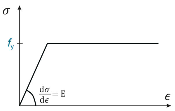
If we assume that stability is not a problem, in other words there is no danger of local or global buckling limiting resistance, then the strength of a member is a function of its cross-section and material strength. Its stiffness is a function of the cross-section and the elastic modulus of the material. These material properties are represented on a stress-strain curve for steel by the initial slope of the curve (up to the elastic limit), and the stress associated with the ‘plateau’ (or, for a material that shows a less bi-linear response than structural steel, the stress at a certain level of ‘proof’ strain). Figure 1 reproduces the simplified bi-linear stress-strain curve that BS EN 1993-1-1¹ says may be used in design for structural steel, illustrating these values.
Ductility is assured when a material can accommodate a significant amount of strain beyond the point at which it reaches its ‘strength’. In other words a long plateau on a stress-strain curve, in compression or tension as appropriate, indicates a material with ductility. Typically, structural steel actually sees an increase in strength along this plateau, as strain hardening occurs. So the ultimate strength of a piece of steel, fu, exceeds its yield strength fy. The rules given in Eurocode 3 are only valid for steels that satisfy certain limits. In clause 3.2.2 these limits are given in terms of the ratio between yield and ultimate strengths, a minimum value for elongation at failure over a certain gauge length, and the ultimate strain that corresponds to the ultimate strength. Although the beneficial effect of strain hardening on section resistance is normally ignored, satisfying these relationships ensures that the assumptions concerning plastic behaviour implicit in some of the Eurocode design rules are not invalidated.
Why may ductility be critical?
The way something fails can be very important. Cars used to be designed with large bumpers and strong sub-structures so they could best resist an impact (and remain relatively unscathed). Today they are designed with crumple zones, that contain materials that can deform, i.e. they are ductile, and in so doing absorb the energy of the impact. Significant local damage is accepted. Examples are considered below to illustrate that in steel structures making a component strong is not always the best answer, and indeed building something that contains components that are stronger than assumed in design could be a problem because the structure would not then fail as intended.
Some examples
Partial strength end plate joints
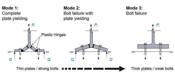
Perhaps the most obvious example of a situation where the materials and components used need to have the correct strength is partial strength (a term that means the resistance of the joint is less than that of either of the connected members) moment resisting joints that adopt end plates, and are assumed to be able to rotate as ‘plastic hinges’. Rotation takes place in the joint, not the connected members, because the joint is the weak link. Such joints contain a number of components, such as welds, bolts, and the end plate itself, as well as the two members the joint connects together. Each of these components has a different resistance, which can be determined using the component method as presented in BS EN 1993-1-8². The lowest of the resistances of the different components defines the moment resistance of the joint itself (along with the lever arm relevant to the critical component). As well as different resistances, the components have different levels of ductility – bolts and welds cannot accommodate large amounts of strain (they are brittle), whereas an end plate deforms plastically out-of-plane, exhibiting yield lines and therefore having significant ductility (Figure 2). The component with the lowest resistance will also dictate the ductility of the joint. The so-called moment connections Green Book P398³ includes some partial-strength standard joints alongside the more usual ‘rigid connections’, and talks about different failure modes for a joint, namely Modes 1, 2 and 3 (see Figure 3). Mode 1 is the most ductile, and Mode 3 the least. Many economically proportioned joints will exhibit Mode 2, meaning a sufficient level of ductility can be achieved. Joints for use in frames designed according to SCI publications concerning semi-continuous braced frames and wind-moment frames4,5 will invariably fail in Mode 2. Conversely, for a joint that is designed to be ‘rigid’ Mode 3 failure may be desirable, because the deformation associated with Mode 2 means the joint may be less rigid than assumed.
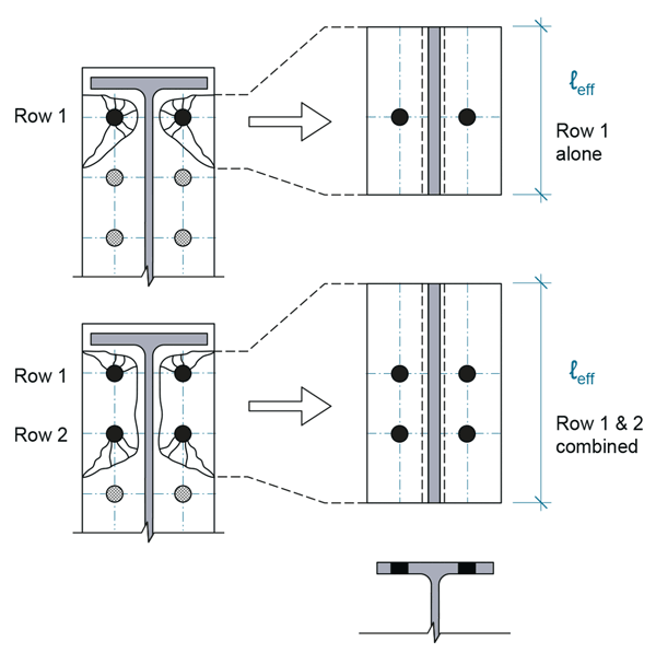
and enabling its resistance to be quantified
However, if one of the components in a joint is supplied ‘over-strength’ it could result in not only the resistance of the joint increasing, but also the failure mode changing. Using an over-strength end plate could result in a joint that was supposed to show ductility, i.e. rotation capacity, becoming brittle because its resistance was then dictated by, say, failure of the bolts. The age of the SCI publications referred to above means the standard details they propose adopt S275 end plates, with plate thicknesses and bolt sizes carefully ‘matched’ to ensure the bolts are stronger than the plates. However, in 2023 there is a reasonable chance that S355 plates might be supplied, not to mention the fact that steel is normally supplied to achieve a minimum yield strength, with no upper limit specified. Bigger bolts, and welds, could be needed to assure the behaviour assumed by the designer, so at the fabrication stage it is important to ensure the correct material has been used. It should be recognised that of course bolts and welds may also be supplied overstrength!
As an aside when considering steel grades, the maximum loads attracted by structural elements supporting others that are subject to blast loads, depend on the ultimate strength of the connected parts. Unlike yield, ultimate strengths are given as minima and maxima in product standards for steel sections and plates e.g. for S355, ultimate strength must be between 470 MPa and 630 MPa for material up to 100 mm thick. There may be instances where the upper bound strength is the relevant one to use for assessing the effect of blast or other accidental loads.
Shear stud resistances and transverse reinforcement in a composite beam
BS EN 1994-1-1⁶ presents rules, through reference to BS EN 1992-1-1⁷ for determining how much transverse reinforcement is needed in a composite beam. Although not explicitly stated, the reinforcement should be chosen as a function of the number and resistance of the shear studs. The purpose of this reinforcement is to ensure that the forces transferred locally from the steel beam into the concrete slab via the shear studs can migrate out into a larger width of slab. The relationship between transverse reinforcement and shear stud forces is much easier to understand in the way BS 5950-3.1 clause 5.6.2 presents the design rule, which is simply that the longitudinal force to be resisted per unit length v is the resistance of the shear connectors (NQ, where N is the number of connectors in a group and Q is the resistance of an individual connector) divided by the longitudinal spacing of the connectors/groups s:

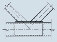
A reason for ‘sizing’ the transverse reinforcement based on the number and resistance of the studs, rather than an applied force, is that failure of the transverse shear plane in a composite beam may not provide the level of ductility (slip capacity) associated with stud failure. Potential planes, as presented in BS EN 1994-1-1, are shown in Figure 4. However, the rules in the codes for plastic design of composite beams assume that the studs have sufficient ductility to redistribute forces between themselves, so it is necessary to avoid non-ductile failure. It is therefore important not to underestimate the resistance of the connectors and by so doing fail to provide sufficient transverse reinforcement. It is also worth noting that even though design with ductile connectors assumes the shear force is equally distributed between them, in reality the studs nearer the support experience higher levels of slip than those near the centre line (for uniform loading). So even when the applied loads do not require all studs to be ‘at capacity’, some of them will be. Assuming a lower force could, in theory, result in insufficient transverse resistance.

Seismic design
Design for seismic conditions is unusual in the UK, however it provides a very good example of the importance of ensuring that the intended ‘weak link’ in a structure is indeed the weak link. The use of I-section beams with notched flanges is common, where the notches ensure that the resistance is lowest at a specific point (where the designer has assumed the plastic hinges will form). This avoids the joints being over-loaded. Some steel frames designed for seismic events also adopt so-called fuses, weak points which are designed to be the focus of damage and can therefore be replaced without the need to replace beams and columns during renovation.
Stainless steel
Stainless steel, particularly austenitic, exhibits significantly more strain hardening behaviour than carbon steel. As an example, this could result in the moment resistance of a beam being underestimated by around 20%, depending on the beam’s cross-section. The strain hardening exhibited by stainless steel can also lead to a large increase in strength following cold working. The yield strength of a cold-formed hollow section made of austenitic stainless steel can be up to 50% greater than that of the preformed material. Depending on how such steels are to be used, designers should beware that this phenomenon does not result in changed, detrimentally, failure modes.
Conclusions
It feels only natural to assume that if something is stronger than assumed in design, it will be more able to support the applied loads than was assumed, and that this can only be a good thing. However, the examples given above show that the relative strengths of structural components that interact with each other is also important – not just their absolute strengths. If the way in which they interact changes as a result of one of them being stronger than expected, it can affect which component is critical. This can potentially change ductile behaviour of the combination of components into brittle behaviour, and although failure could be at a higher applied load than anticipated, changing the critical component could have very negative consequences.
- BS EN 1993-1-1:2005. Eurocode 3: Design of steel structures. General rules and rules for buildings BSI, 2005
- BS EN 1993-1-8. Eurocode 3: Design of steel structures. Design of joints BSI, 2005
- P398 Joints in steel construction: Moment-resisting joints to Eurocode 3 SCI and BCSA, 2015
- P183 Design of semi-continuous braced frames SCI, 1997
- P263 Wind-moment design of low raise frames SCI, 1999
- BS EN 1994-1-1:2004. Eurocode 4: Design of composite steel and concrete structures. General rules and rules for buildings (incorporating corrigendum April 2009) BSI, 2004
- BS EN 1992-1-1:2004. Eurocode 2: Design of concrete structures. General rules and rules for buildings (incorporating corrigendum January 2008 and November 2010) BSI, 2004


