Technical
AD 381: Fatigue assessment of non-standard bridge details
The Advisory Desk has been made aware of some instances of fatigue failure in cross beam to main girder connections, arising from the use of a ‘non-standard’ fatigue detail. Although the instances were specific to a particular type of bridge structure, there are some general lessons for detailing of structures that must be designed for fatigue.
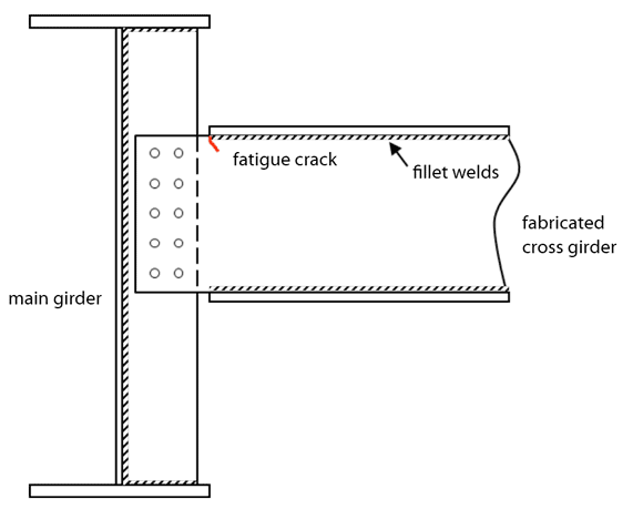
Fig. 1. Schematic arrangement of failed detail
An instance where failure occurred is shown schematically in Figure 1. The cross beam is a plate girder, with two flanges welded to a web plate of constant depth; the web plate is bolted to a transverse stiffener on the main girder. The web to flange welds simply stop at the end of the flange. Failure occurred by cracking in the web at the end of the fillet welds. Such a detail is not covered by any of the details in EN 1993-1-9 (Tables 8.1 to 8.10) but is likely to be at the lower end of the range of fatigue categories. It is not known what category the designer adopted.
The lesson from this experience is to avoid details not closely similar to one of the details in the EN 1993-1-9 Tables, wherever possible. If a non-standard detail is to be used, then it is recommended that testing be carried out to determine the category of the non-standard detail.
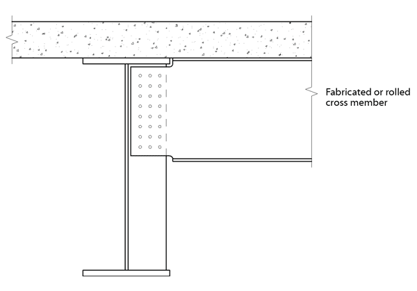
Fig. 2. Revised Figure 8.9 in P356, showing notches at both top and bottom flanges of cross member
A more common occurrence of a lapped cross beam to main girder detail occurs in composite ladder deck bridges, as illustrated in SCI publication P356. In the original publication, the web was notched at the top, to avoid the main girder flange, and this avoids the non-standard fatigue detail. But the original publication does not show a similar notch at bottom flange detail: this does introduce the non-standard detail described above and it should be avoided by notching the web at the bottom as well as at the top. The revised detail in P356 is shown in Figure 2.
The introduction of a notch in the web require the application of a stress concentration factor (SCF) when calculating the stress range in the web, but such a notch is not exactly covered by the advice in PD 6695-1-9, clause 7. It is likely that a SCF in excess of 2 will be necessary but designers must make their own assessment of the appropriate SCF for their particular detail.
The second lesson is, therefore, that where a SCF is needed but there is no published advice for the particular detail, the designer must consider carefully what value would be appropriate: finite element modelling or testing would be a suitable means of assessing the SCF.
Publications P356 and P357 have been modified on Steelbiz, to show the notch at the lower edge of the web in lapped cross beam connections and a corrigendum is also available from Steelbiz.
Contact: David Iles
Tel: 01344 636525
Email: advisory@steel-sci.com