50 & 20 Years Ago
40 Years Ago: Football stand for 1966 World Cup Series
Taken from Building with Steel, 1965

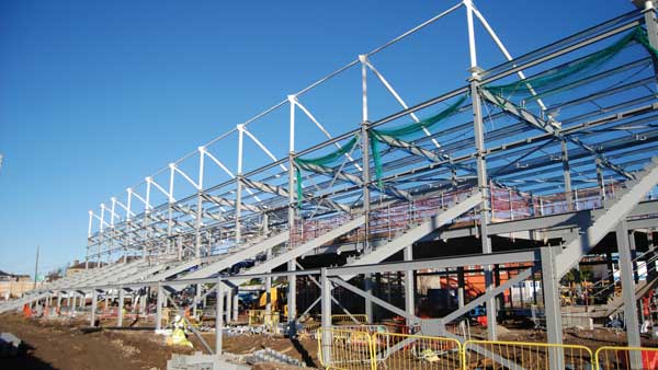
Manchester United FC new stand

Stages in the erection of the new Stand for Manchester United Football Club. Twin pairs of channel shear connectors embedded in top of concrete columns

Lifting the first section of the truss by tower crane

Hinge connecting bottom boom to concrete column

The first quadrant of the Stand sheeted
The directors of Manchester United Football Club had for some time been thinking in terms of developing the north side of the ground but it was not until late in 1963 that their architects got a go ahead for a definite scheme.
This was to accommodate 10,500 seats without reducing the capacity of the ground and was achieved by building out over the ground level concourse at the back of the existing terraced bank as far as the boundary wall.
As the scheme also included the unique feature of private boxes with rear entrance at the back of the stand and necessitated a cantilever roof it presented a difficult structural problem in the limited space available for counterbalancing the cantilever.
Many structural forms were explored, particular efforts being made to devise a stayed cantilever solution. The lack of space coupled with reversal of forces by wind uplift defeated such a scheme and the form adopted is basically the simplest possible.
Various materials of construction were considered and several subjected to cost by tender. It became very evident that maximum economy would be achieved by choosing the cheapest and lightest satisfactory roof sheeting – 18 gauge long length aluminium trough section – and designing the roof structure around that.
Initially it was felt that sections of tubular steelwork would prove economical and the first truss design was based on them.
Tenders showed, however, that the fabrication, erection and protection factors outweighed the saving in materials and therefore standard steel sections were used instead, with universal columns for the top and bottom booms, starred angles for the latticing members and universal beams for the purlins.
Mild steel was adopted in preference to high yield stress steel in order to limit deflections. Welding runs along the main axis have been used for shop connections and high strength friction grip bolts for site fixing. Welds were satisfactorily subjected to radiographic examination.
Protection of the steelwork was achieved by blast cleaning followed immediately by weldable zinc rich epoxy priming and later by micaceous iron oxide finishing paint.
The roof decking has been placed at the bottom of the truss for several reasons – compression boom restraint for the natural gravitational condition, internal appearance, easy access for maintaining the majority of the steelwork and natural roof drainage.
As wind uplift can almost completely reverse the maximum stress distribution the top boom also required buckling restraint. Locally high wind pressure from gusting is spread by the fascia and two inclined transverse stiffening girders. The fascia also breaks up laminar wind flow and reduces air pressure on the roof.